MAN00000772_SI-G200BB_SVCPDFA.pdf - 第245页
Calibration HLGB-1031 1-01 Pickup Position Setup SHEET 1/9 Pickup Position Setup Pickup position setup can be perform ed at three locations on the front cassette table (Z106, Z120, Z139) and at three locations on the rea…
Calibration
HLGB-10310-01
Fixed Camera Rcg Height Calibration
SHEET
5/5
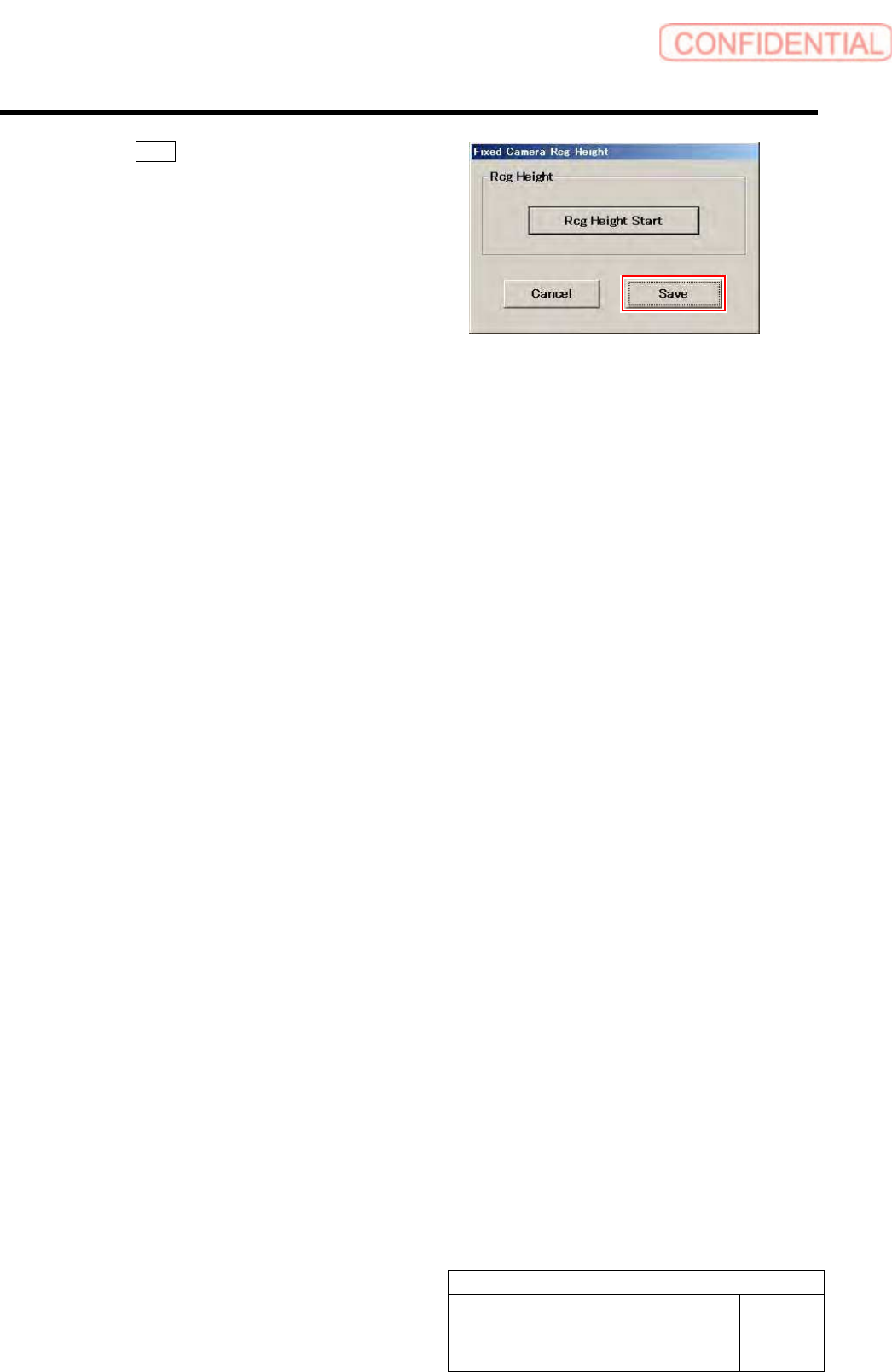
14 Click the Save button.
The fixed camera rcg height is saved and the Fixed
Camera Rcg Height screen closes.
15 Finish fixed camera recognition height search.
1. Close the calibration menu screen to return the unit to the origin.
2. Remove the fixed camera jig base and length reference nozzle jig.
3. Install the cooling fan for fixed camera to the previous position.
4. Install the shooter and the lower cover.
Calibration
HLGB-10311-01
Pickup Position Setup
SHEET
1/9
Pickup Position Setup
Pickup position setup can be performed at three locations on the front cassette table (Z106, Z120,
Z139) and at three locations on the rear cassette table (Z106, Z120, Z135).
Perform pickup position setup for tray specification only on the rear side cassette table (Z101, Z108,
Z117).
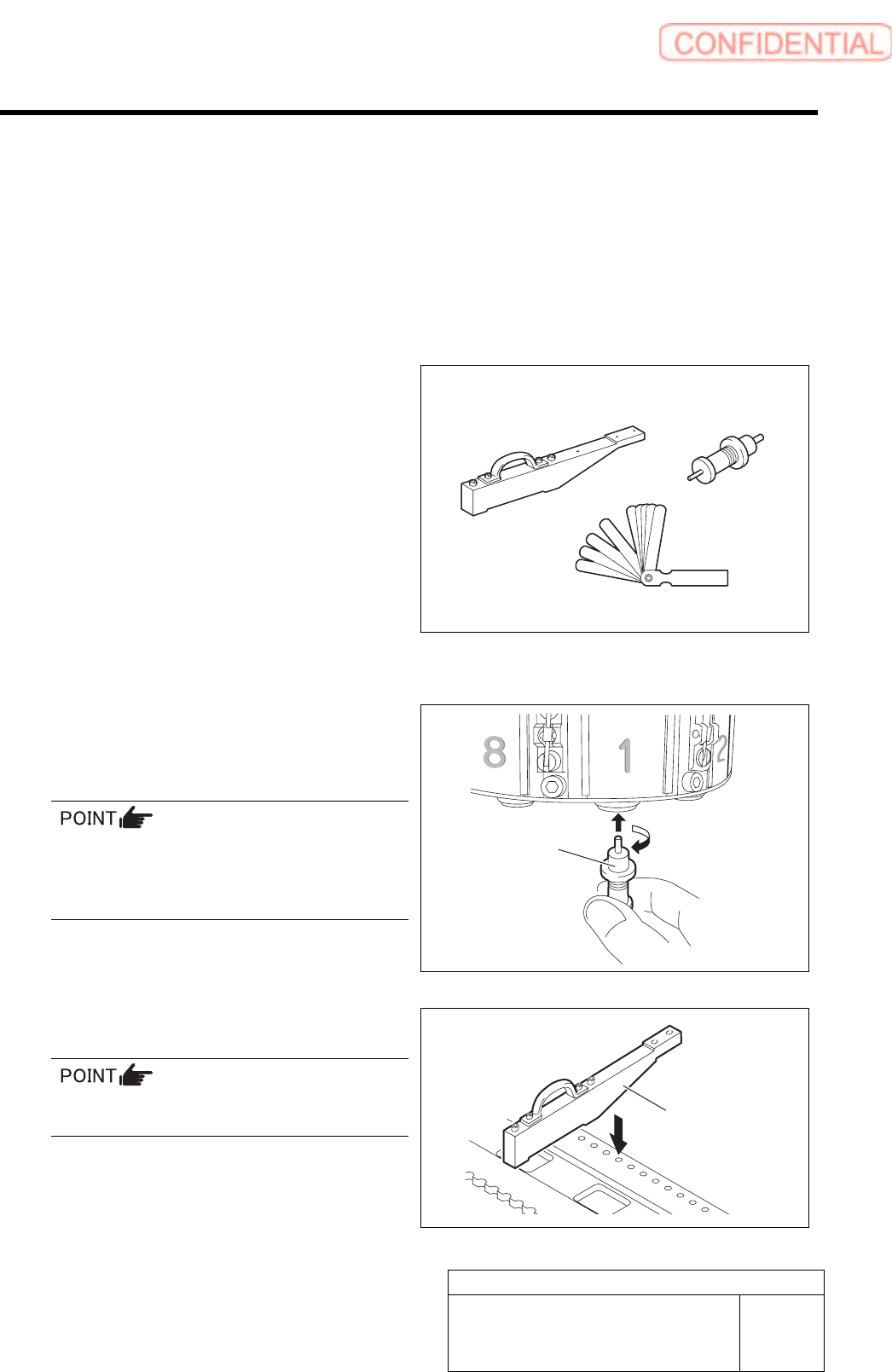
[Necessary jigs]
• Pickup point Jig
• Length reference nozzle jig
• Thickness gauge
[Preparation before work]
1 Set the jig.
1. Install the length reference nozzle jig
to the turret No.1.
When installing the nozzle, insert it while
slowly turning.
After inserting the nozzle, check that it is not
drawn out by pulling downward.
2. Set pickup point jig to Z106 on the
cassette table.
There should be no gap between the feed
adjusting jig and the cassette table.
Pickup point Jig
Length reference
nozzle jig
Thickness gauge
Length reference
nozzle jig
Pickup point Jig
Calibration
HLGB-10311-01
Pickup Position Setup
SHEET
2/9
2 Press the [ORG] button on the operation panel to perform origin position return.
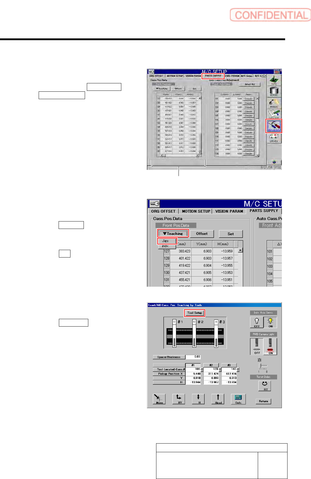
3 Display a PARTS SUPPLY screen.
1. Click in an order of M/C SETUP menu
PARTS SUPPLY tab.
Cassette position coordinates are displayed on
left part of the PARTS SUPPLY screen.
4 Display a Front/All Cass. Pos. Teaching by
Tools screen.
1. Click the Teaching button on the Front
Pos. Data to display a drop down
menu.
2. Click the Jigs in the drop down menu.
The Front/All Cass. Pos. Teaching by Tools
screen is displayed.
5 Set the jig.
1. Click the Tool Setup button.
Tool Setup screen is displayed.
Cassette position coordinates