MAN00000772_SI-G200BB_SVCPDFA.pdf - 第260页
Calibration HLGB-10313-01 Mount Accuracy Calibration SHEET 3/1 1 6 Place the glass PWB with double-stick t ape on the conveyor for positio ning. 7 Place the part s cassette on any supply unit. Glass PWB
Calibration
HLGB-10313-01
Mount Accuracy Calibration
SHEET
2/11
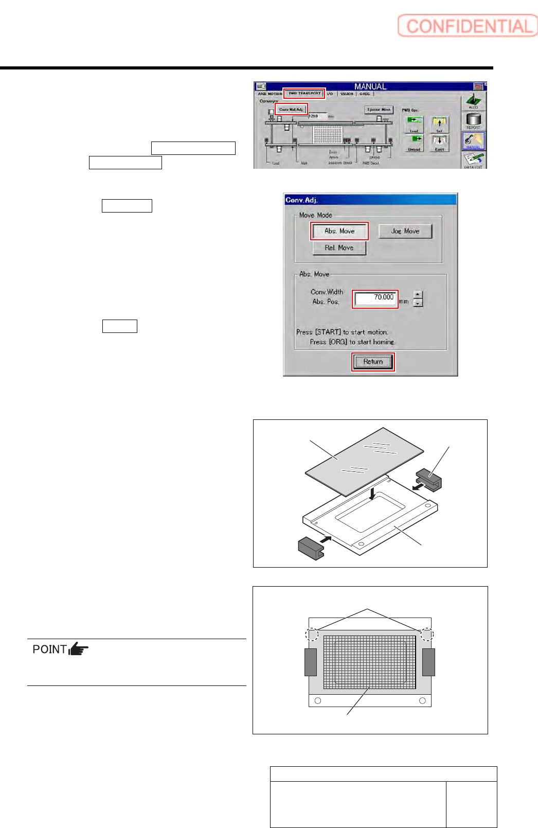
3 Change the conveyer width to 70 [mm], and
then align the PWB stopper and the locator
pin position with the glass PWB frame.
1. Click in an order of
PWB TRANSPORT
tab Conv. Wid. Adj. button.
Conv. Adj. screen is displayed.
2. Click the Abs. Move button.
3. Input “70” into the input box of the
Conv. Width Abs. Pos.
4. Press the [START] button on the
operation panel.
Conveyor width is widened to the position of 70
mm.
5. Click the Return button to close the
Conv. Adj. screen.
4 Set the eight BF1305R nozzles onto the
nozzle cartridge.
5 Prepare a glass PWB for simple
measurement.
1. Put glass PWB on glass PWB frame
and hold it with clamp.
2. Attach double-stick tape on area of the
glass PWB in the figure.
Attach the double-stick tape paying attention to
the position and tape attachment area.
UP UP
Glass PWB
Clamp
Glass PWB frame
“UP” mark
Double-stick tape attachment area
Calibration
HLGB-10313-01
Mount Accuracy Calibration
SHEET
3/11
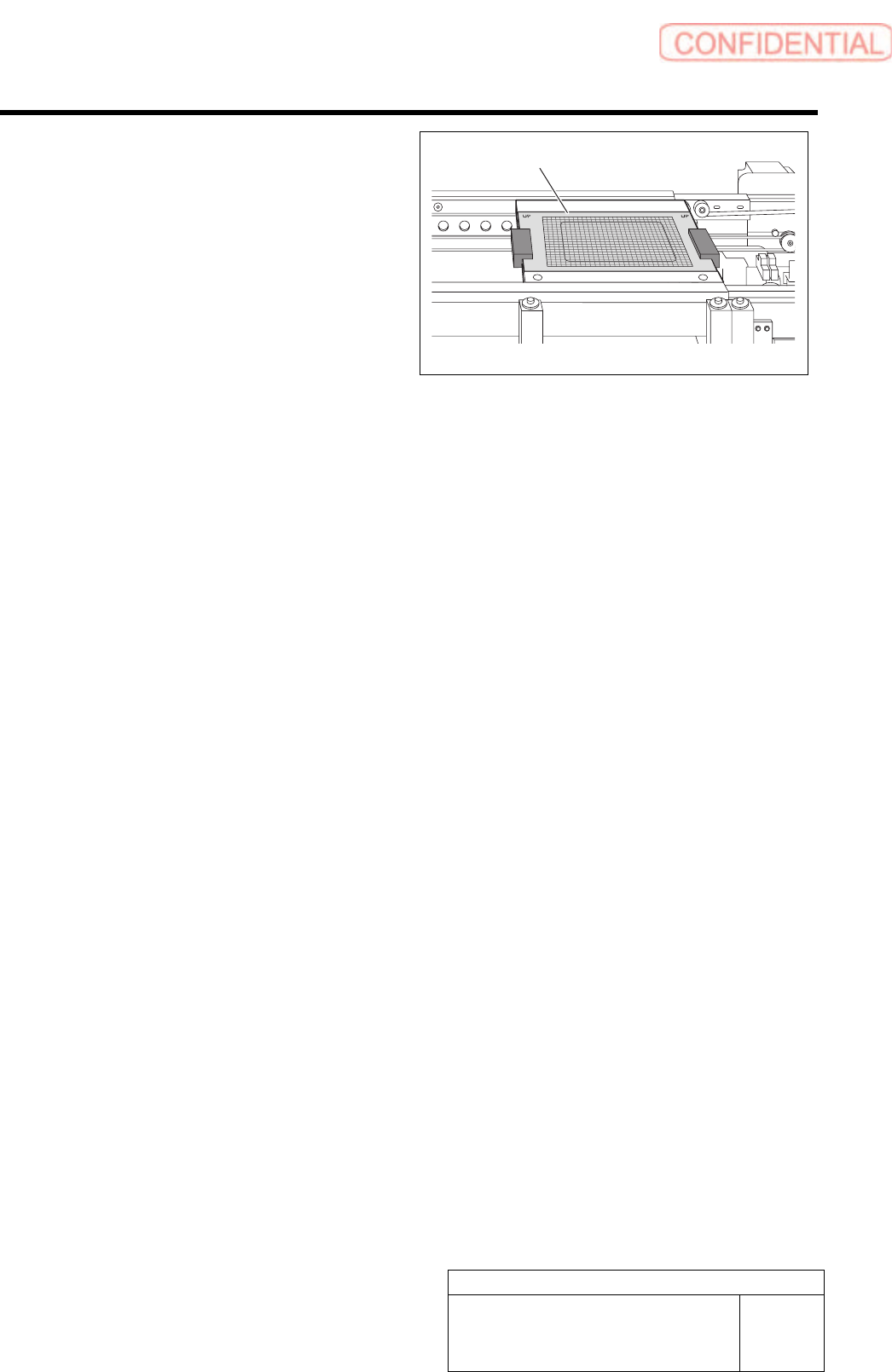
6 Place the glass PWB with double-stick tape
on the conveyor for positioning.
7 Place the parts cassette on any supply unit.
Glass PWB
Calibration
HLGB-10313-01
Mount Accuracy Calibration
SHEET
4/11
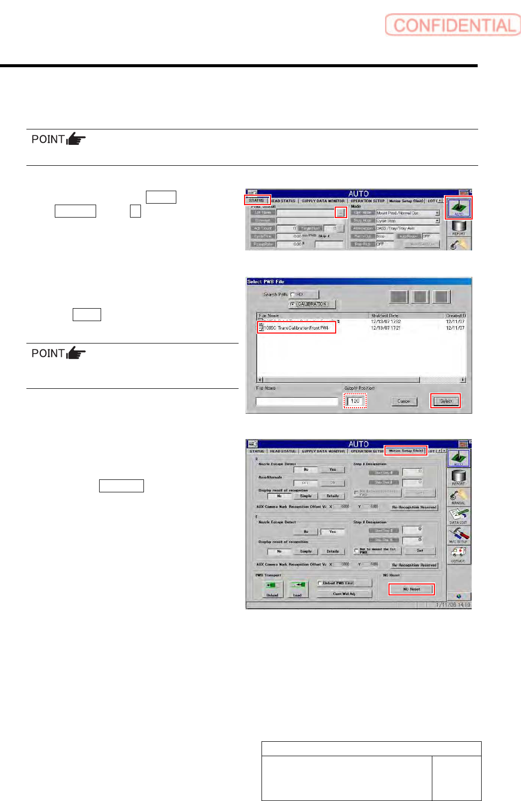
[Transcription calibration]
1 Read machine data of “1005C TransCalibrationFront.PW4.”
To execute the calibration for the rear head, select “1005C transCalibrationRear.PW4”.
1. Click in an order of AUTO menu
STATUS tab … button.
Select PWB File screen is displayed.
2. Select the “1005C
TransCalibrationFront.PW4” and click
the Select button.
In the Supply Position field, enter the supply
unit number on which you placed the cassette.
2 Perform NC reset and then check MOTION
Setup.
1. Click the NC Reset button on the
MOTION Setup (Unit) screen.