MAN00000772_SI-G200BB_SVCPDFA.pdf - 第261页
Calibration HLGB-10313-01 Mount Accuracy Calibration SHEET 4/1 1 [T ranscription calibration] 1 Read machine data of “ 1005C T ransCal ibrationFront.PW4. ” T o execute the calibration for the rear hea d , select “1005C t…
Calibration
HLGB-10313-01
Mount Accuracy Calibration
SHEET
3/11
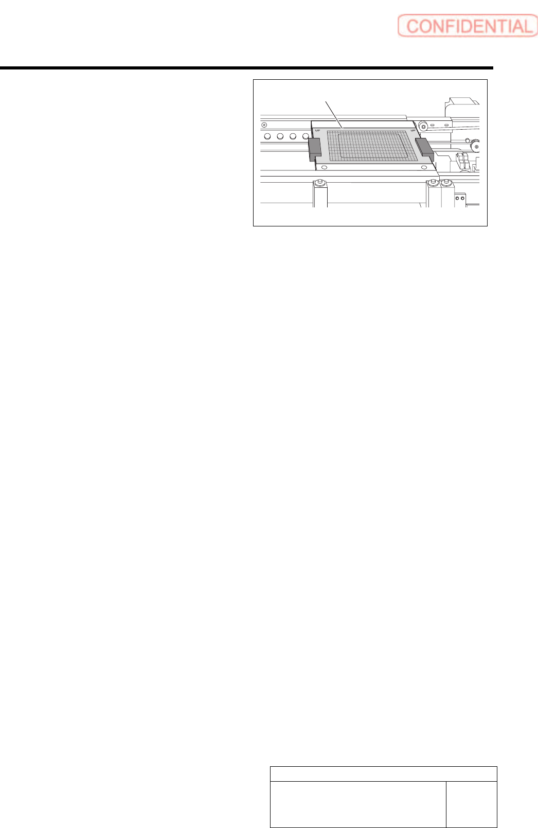
6 Place the glass PWB with double-stick tape
on the conveyor for positioning.
7 Place the parts cassette on any supply unit.
Glass PWB
Calibration
HLGB-10313-01
Mount Accuracy Calibration
SHEET
4/11
[Transcription calibration]
1 Read machine data of “1005C TransCalibrationFront.PW4.”
To execute the calibration for the rear head, select “1005C transCalibrationRear.PW4”.
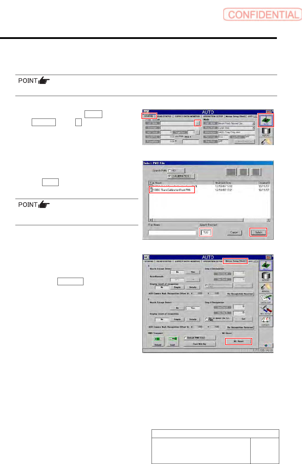
1. Click in an order of AUTO menu
STATUS tab … button.
Select PWB File screen is displayed.
2. Select the “1005C
TransCalibrationFront.PW4” and click
the Select button.
In the Supply Position field, enter the supply
unit number on which you placed the cassette.
2 Perform NC reset and then check MOTION
Setup.
1. Click the NC Reset button on the
MOTION Setup (Unit) screen.
Calibration
HLGB-10313-01
Mount Accuracy Calibration
SHEET
5/11
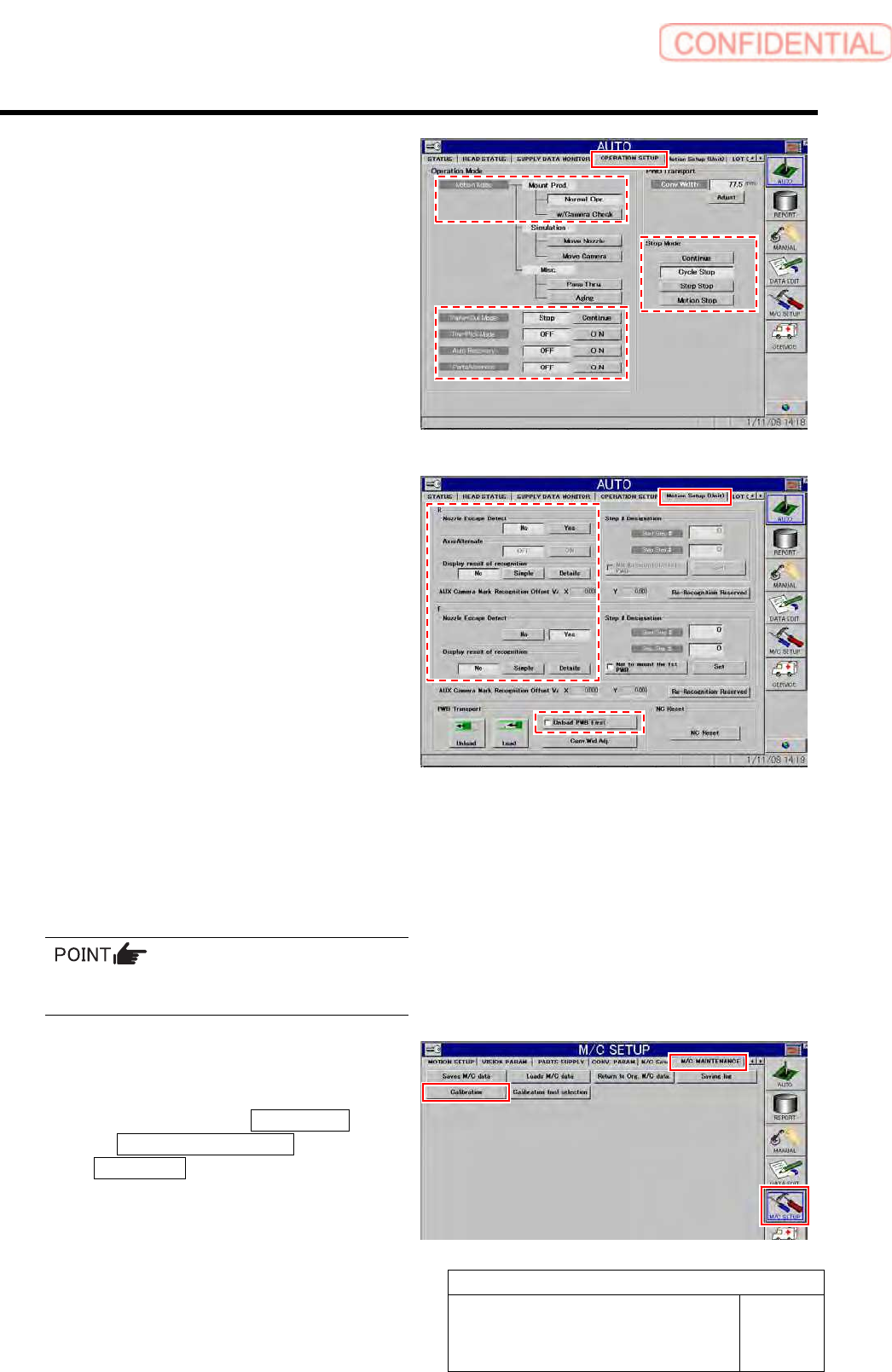
2. Display OPERATION SETUP to check
that settings are as follows.
Motion Mode: Normal Opr.
Parts-Out Mode: Stop
Pre-Pick Mode: OFF
Auto Recovery: OFF
Parts Alternate: OFF
Stop Mode: Cycle Stop
3. Display Motion Setup (Unit) screen to
check that settings are as follows.
Nozzle Escape Detect: Yes
Display result of recognition: No
Unload PWB First: Turned off
3 Press [START] button on the operation
panel and fit parts onto the simple
measuring glass PWB.
Fitting operation is performed for one cycle, and then
the unit stops.
Make sure the wrong pickup or pickup error
does not occur.
4 When fitting is completed without error,
display the accuracy correction screen.
1. Click in an order of M/C SETUP menu
M/C MAINTENANCE tab
Calibration button.
A confirmation window to clear machine data is
displayed.