MAN00000772_SI-G200BB_SVCPDFA.pdf - 第276页
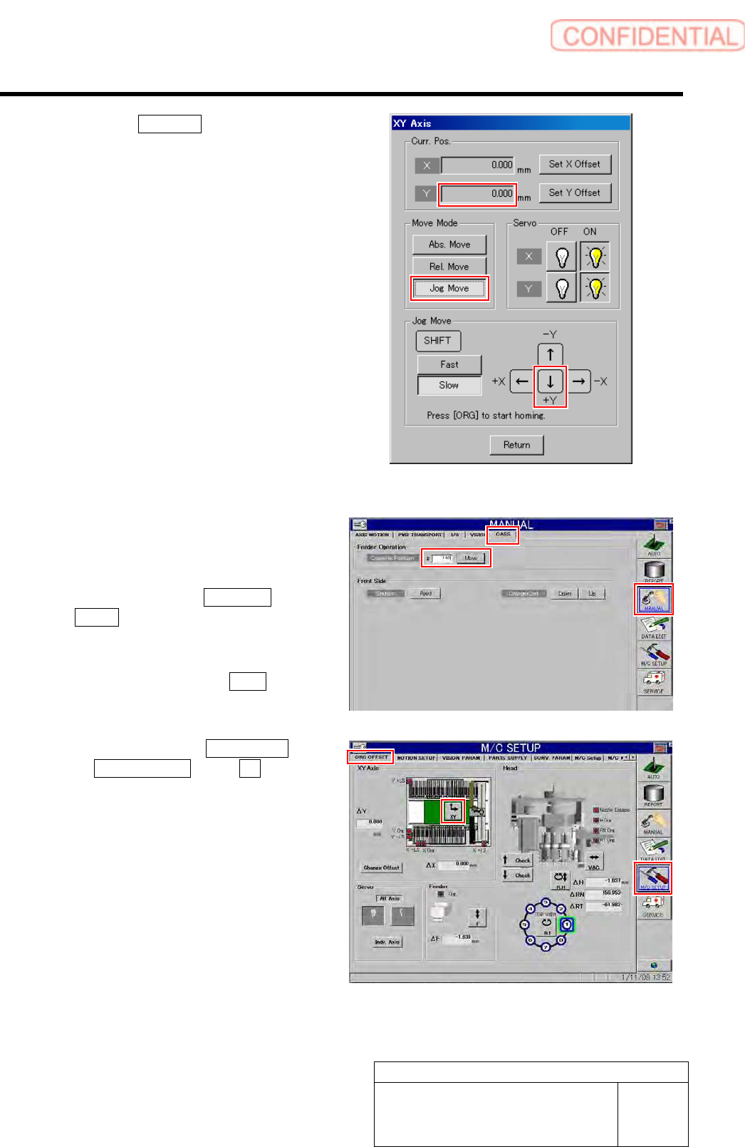
Calibration HLGB-10314-01 XY A xis Sof tware Limit Setup SHEET 8/1 1 5. Click the Jog Move button. 6. Press the lower cursor to jog-move Y axis in positiv e direction. When Y axis moves to the software limit position, al…
Calibration
HLGB-10314-01
XY Axis Software Limit Setup
SHEET
7/11
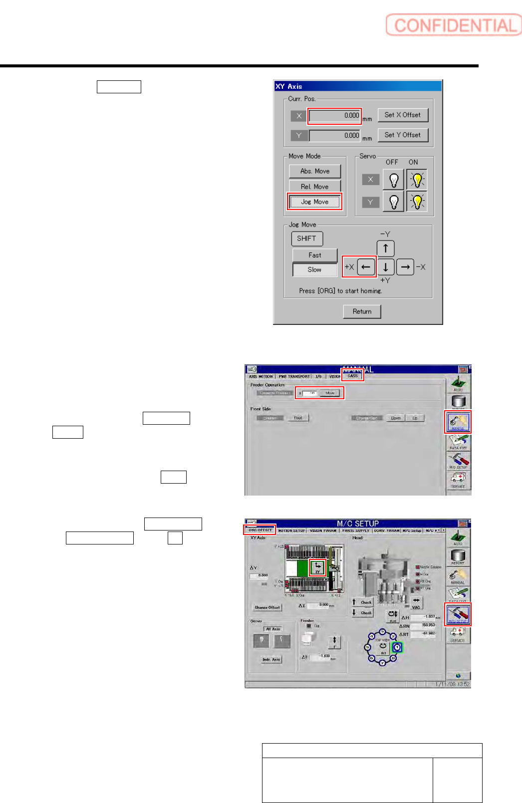
5. Click the Jog Move button.
6. Press the right cursor to jog-move X
axis in positive direction.
When X axis moves to the software limit
position, alarm is displayed.
7. Press the [RESET] button on the
operation panel to cancel the alarm.
8. Check that the present position of X
axis displayed on the operation screen
of XY axis is same as the value
calculated in the setup procedure 1.
3 Check Y coordinate of the software limit
sensor in Y axis positive direction.
1. Press the [ORG] button on the
operation panel to perform origin
position return.
2. Click in an order of MANUAL menu
CASS. tab.
Cassette operation screen is displayed.
3. Input “101” into the cassette position
input box and click the Move button.
The head moves to the cassette position “101”.
4. Click in an order of M/C SETUP menu
ORG OFFSET tab XY button.
XY Axis screen is displayed.
Calibration
HLGB-10314-01
XY Axis Software Limit Setup
SHEET
8/11
5. Click the Jog Move button.
6. Press the lower cursor to jog-move Y
axis in positive direction.
When Y axis moves to the software limit
position, alarm is displayed.
7. Press the [RESET] button on the
operation panel to cancel the alarm.
8. Check that the present position of Y
axis displayed on the operation screen
of XY axis is same as the value
calculated in the setup procedure 1.
4 Check X coordinate of the software limit
sensor in X axis negative direction.
1. Press the [ORG] button on the
operation panel to perform origin
position return.
2. Click in an order of MANUAL menu
CASS. tab.
Cassette operation screen is displayed.
3. Input “140” into the cassette position
input box and click the Move button.
The head moves to the cassette position “140”.
4. Click in an order of M/C SETUP menu
ORG OFFSET tab XY button.
XY Axis screen is displayed.
Calibration
HLGB-10314-01
XY Axis Software Limit Setup
SHEET
9/11
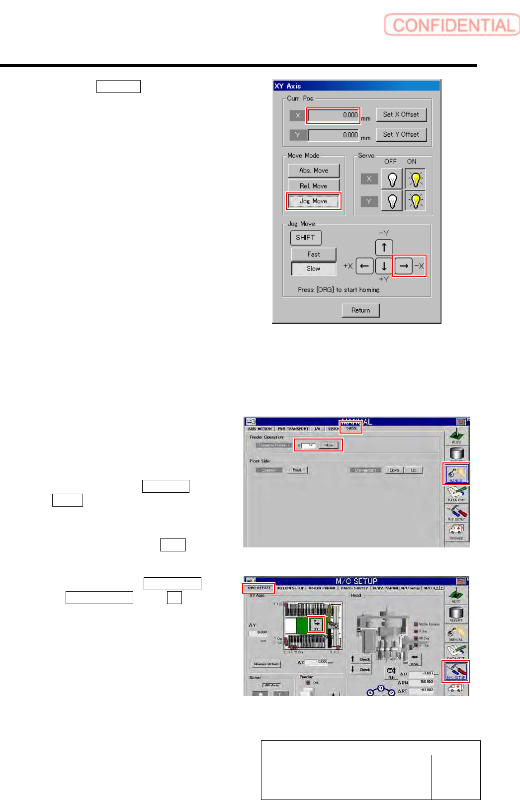
5. Click the Jog Move button.
6. Press the right cursor to jog-move X
axis in negative direction.
When X axis moves to the software limit
position, alarm is displayed.
7. Press the [RESET] button on the
operation panel to cancel the alarm.
8. Check that the present position of X
axis displayed on the operation screen
of XY axis is same as the value
calculated in the setup procedure 1.
[Front and rear collide side software limit checking procedure]
1 Check Y coordinate of the software limit
sensor in Y axis negative direction on the
rear side.
1. Press the [ORG] button on the
operation panel to perform origin
position return.
2. Click in an order of MANUAL menu
CASS. tab.
Cassette operation screen is displayed.
3. Input “101” into the cassette position
input box and click the Move button.
The head moves to the cassette position “101”.
4. Click in an order of M/C SETUP menu
ORG OFFSET tab XY button.
XY Axis screen is displayed.