MAN00000772_SI-G200BB_SVCPDFA.pdf - 第285页
Calibration HLGB-10316-01 Measuring Parallelism of Reference Pin and Dependent Pin SHEET 4/4 9. In a state that the dependent pin is on the center of the “PCBOARD DISPLA Y” screen, check the coordinat e value of Y axi s …
Calibration
HLGB-10316-01
Measuring Parallelism of Reference
Pin and Dependent Pin
SHEET
3/4
5 Check Y axis coordinate at a position where
dependent pin is displayed on the center of
the “PCBOARD DISPLAY” screen.
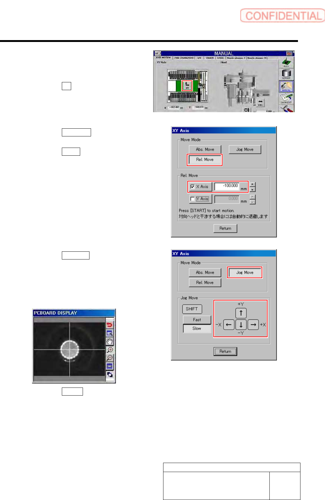
1. Click the XY button.
XY Axis screen is displayed.
2. Click the Rel. Move button in the
move mode.
3. Click the X axis and put checkmark.
4. Input “-100” into X axis box.
5. Press the [START] button on the
operation panel.
The PWB camera moves to above the dependent
pin on a position of 100mm from the reference
pin.
6. Click the Jog Move button in the move
mode.
7. Press the cursor key to move XY axes
so that the dependent pin is displayed
on the center of the “PCBOARD
DISPLAY” screen.
8. Click the Return button to close XY
axes screen.
Calibration
HLGB-10316-01
Measuring Parallelism of Reference
Pin and Dependent Pin
SHEET
4/4
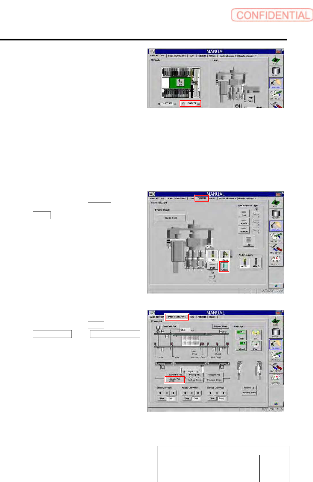
9. In a state that the dependent pin is on
the center of the “PCBOARD
DISPLAY” screen, check the
coordinate value of Y axis on the axis
operation screen, and record the value.
6 Repeat the procedure 5, and record the coordinate values of Y axis on the respective positions of
distances 100/200/300/400/450 mm from the reference pins.
7 At this time, adjust position of the dependent pin so that parallelism of the dependent pin to the
reference pin is “0.15 mm” or less.
Standard value: 0.15 mm
8 After adjusting position of the dependent pin, recheck the coordinate values of Y axis at each
position of 100/200/300/400/450 mm.
9 Light off the PWB camera light.
1. Click in an order of VISION tab
Check button.
The pickup camera light lights off.
10 Lower the reference pin.
1. Click in an order of PWB
TRANSPORT tab Locator Pin Down
button.
The reference pin is lowered.
Calibration
HLGB-10317-01
Parts Discard Position Adjustment
SHEET
1/1
Parts Discard Position Adjustment
Perform this working on both heads on the front side and rear side.
[Procedure]
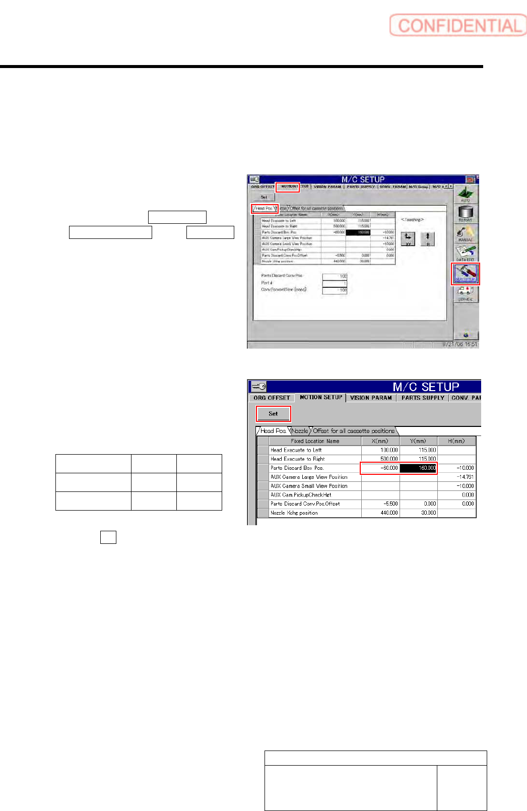
1 Display a motion setup screen for head
position.
1. Click in an order of M/C SETUP menu
MOTION SETUP tab Head Pos.
tab.
2 Change the X, Y values of the Parts Discard
Box Position.
1. Input the following values into the
setting space of the Parts Discard Box
Position.
X Y
Front side PC -60.0 160.0
Rear side PC 60.0 -180.0
2. Click the Set button.