MAN00000772_SI-G200BB_SVCPDFA.pdf - 第301页
Adjustment HLGB-10405-01 Adjustment of H A xis Lower End OT Sensor (H-CW) SHEET 1/2 Adjustment of H Axis Lower End OT Sensor (H-CW) Perform this working on both heads on the front sid e and rear side. [Necessary jigs] • …
Adjustment
HLGB-10404-01
Adjustment of H Axis Upper End OT
Sensor (H-CCW)
SHEET
3/3
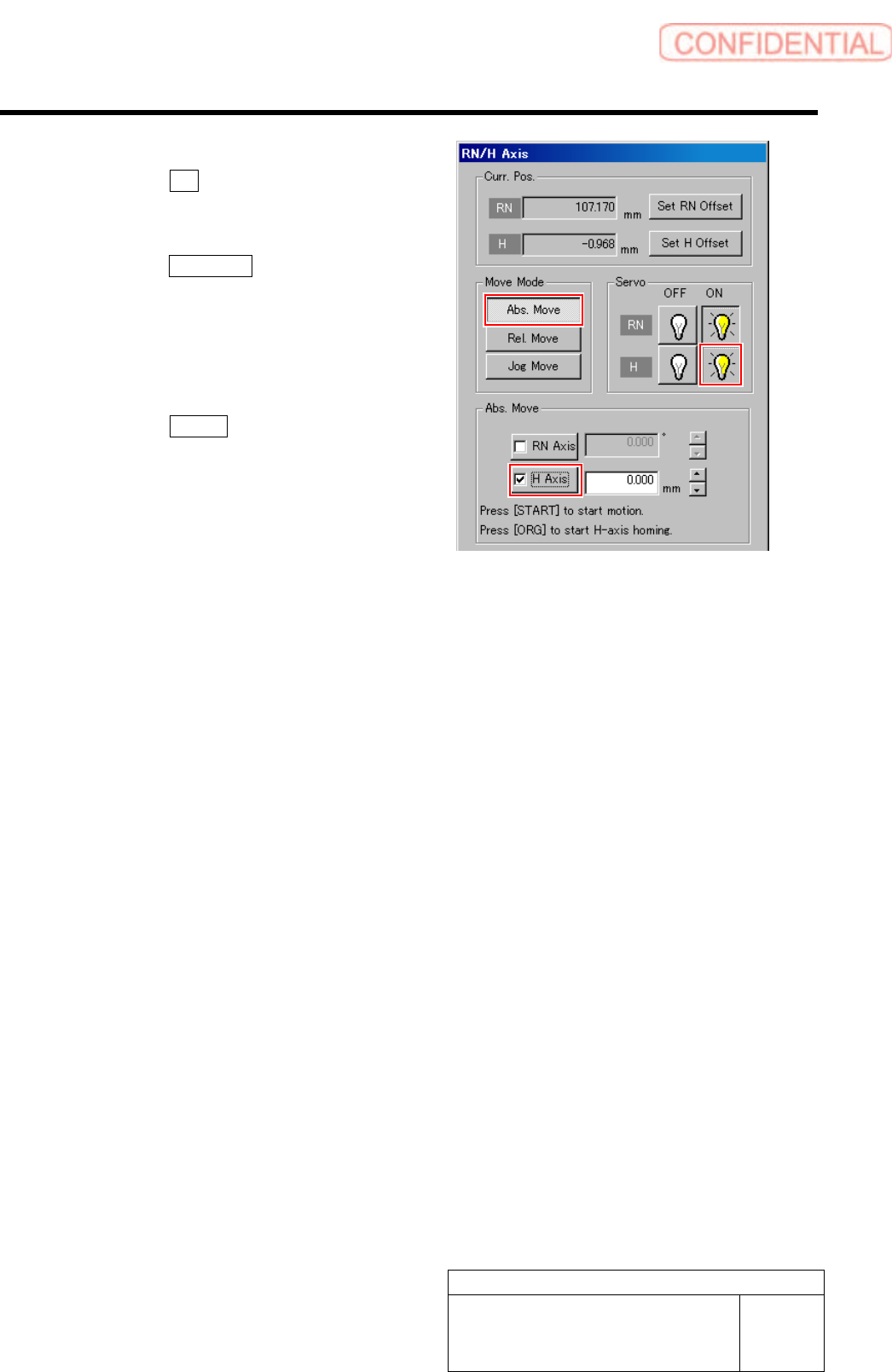
8 Perform origin position return of the H axis.
1. Click the ON button for the H axis
servo on the RN/H Axis screen.
Servo for H axis is turned on.
2. Click the Abs. Move button for move
mode and put checkmark on H axis.
3. Press the [ORG] button on the
operation panel.
Origin position return of the H axis is
performed.
4. Click the Return button to close the
RN/H Axis screen.
Adjustment
HLGB-10405-01
Adjustment of H Axis Lower End OT
Sensor (H-CW)
SHEET
1/2
Adjustment of H Axis Lower End OT Sensor (H-CW)
Perform this working on both heads on the front side and rear side.
[Necessary jigs]
• H Axis sensor adjusting Jig
(L=26.6 mm, 26.5 mm)
[Procedure]
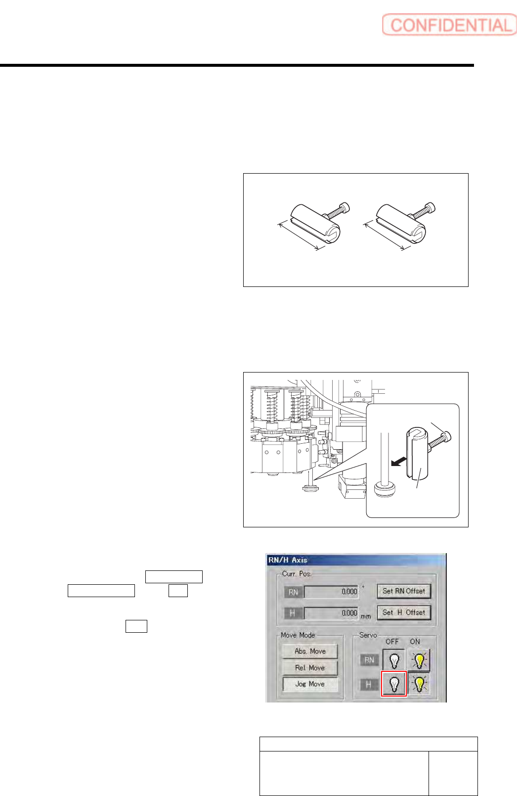
1 Move the inner shaft of the turret No.1 to
right below the H axis pusher.
2 Install the H axis sensor adjusting jig to the
inner shafts of turret No.1.
1. Push the H axis pusher from the upper
by hand, and push down the inner
shaft.
2. Pinch the H axis sensor adjusting jig
(L=26.6 mm) between the turret and
inner shaft.
3. Remove the cap screw for H axis
sensor adjusting jig.
3 Turn off the H axis servo.
1. Click in an order of M/C SETUP menu
ORG OFFSET tab R.H button.
RN/H Axis screen is displayed.
2. Click the servo OFF button for H axis.
Servo for H axis is turned off.
H Axis sensor adjusting Jig
26.6 mm 26.5 mm
H axis sensor
adjusting jig
Cap screw
Adjustment
HLGB-10405-01
Adjustment of H Axis Lower End OT
Sensor (H-CW)
SHEET
2/2
4 Loosen the cap screws (2-M3) on sensor
bracket for the H axis lower end OT sensor
to move the bracket downward (to lower
end).
The LED for H axis lower end OT sensor is lighting
up.
・ Keep the cap screws (2-M3) in temporarily
tightened state.
・ When the H Axis lower end OT sensor is
obstructed, the LED lights off.
5 Move the sensor bracket for the H axis lower end OT sensor upward little by little, tighten the cap
screws (2-M3) at a position of boundary where the lighting LED extinguishes, and secure the
sensor bracket.
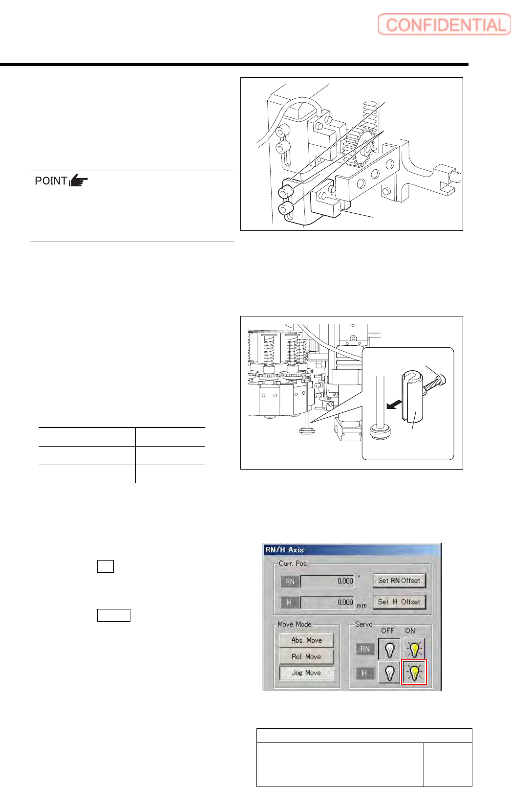
6 Change the H axis sensor adjusting jig
installed on the inner shaft of the turret No.1
to a jig of 26.5 mm.
7 Check that the lighting LED for the H axis
lower end OT sensor Lights-up at this time.
Sensor setting: Dark ON
Jig used State of LED
Jig 1 (L=26.6 mm) Extinguish
Jig 2 (L=26.5 mm) Lights-up
8 When raising and lowering the dog for the H axis sensor, check that the H axis upper end OT
sensor does not interfere with the ORG sensor cable.
9 Return the H axis servo back to on.
1. Click the ON button for the H axis
servo on the RN/H Axis screen.
Servo for H axis is turned on.
2. Click the Return button to close the
RN/H Axis screen.
Sensor bracket
Cap screw
H axis lower end
OT senso
r
H axis sensor
adjusting jig
Cap screw