MAN00000772_SI-G200BB_SVCPDFA.pdf - 第303页
Adjustment HLGB-10406-01 FF/FR A xis Z-Phase Matchin g SHEET 1/4 FF/FR Axis Z-Phase Matching [Necessary jigs] • Digita l operator ALARM RESET SCROLL YASKA WA MODE/SET J OG SVON READ SERVO D ATA WRITE SERVO S VCN TG ON RE…
Adjustment
HLGB-10405-01
Adjustment of H Axis Lower End OT
Sensor (H-CW)
SHEET
2/2
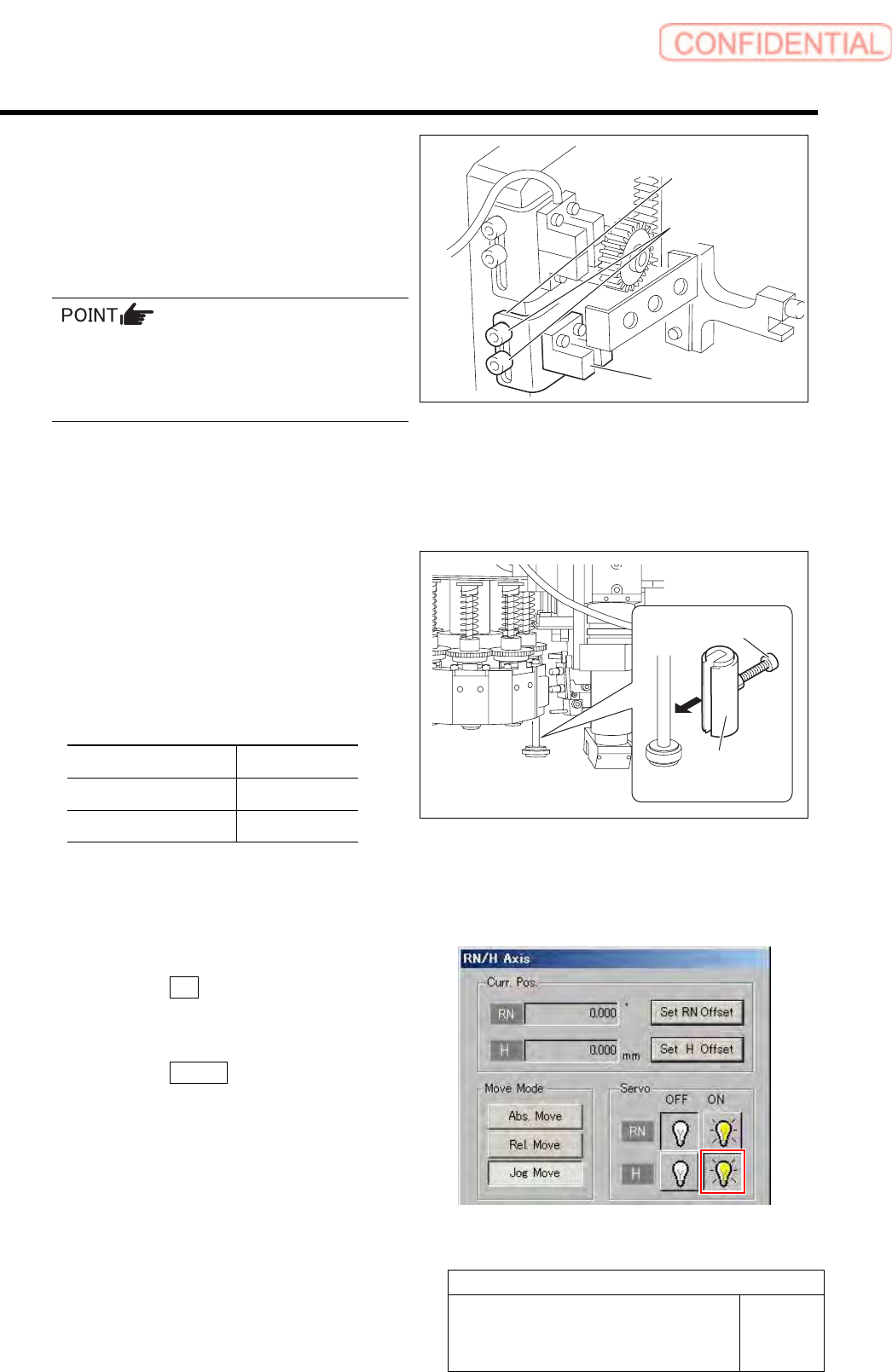
4 Loosen the cap screws (2-M3) on sensor
bracket for the H axis lower end OT sensor
to move the bracket downward (to lower
end).
The LED for H axis lower end OT sensor is lighting
up.
・ Keep the cap screws (2-M3) in temporarily
tightened state.
・ When the H Axis lower end OT sensor is
obstructed, the LED lights off.
5 Move the sensor bracket for the H axis lower end OT sensor upward little by little, tighten the cap
screws (2-M3) at a position of boundary where the lighting LED extinguishes, and secure the
sensor bracket.
6 Change the H axis sensor adjusting jig
installed on the inner shaft of the turret No.1
to a jig of 26.5 mm.
7 Check that the lighting LED for the H axis
lower end OT sensor Lights-up at this time.
Sensor setting: Dark ON
Jig used State of LED
Jig 1 (L=26.6 mm) Extinguish
Jig 2 (L=26.5 mm) Lights-up
8 When raising and lowering the dog for the H axis sensor, check that the H axis upper end OT
sensor does not interfere with the ORG sensor cable.
9 Return the H axis servo back to on.
1. Click the ON button for the H axis
servo on the RN/H Axis screen.
Servo for H axis is turned on.
2. Click the Return button to close the
RN/H Axis screen.
Sensor bracket
Cap screw
H axis lower end
OT senso
r
H axis sensor
adjusting jig
Cap screw
Adjustment
HLGB-10406-01
FF/FR Axis Z-Phase Matching
SHEET
1/4
FF/FR Axis Z-Phase Matching
[Necessary jigs]
• Digital operator
ALARM
RESET
SCROLL
YASKAWA
MODE/SET
JOG
SVON
READ
SERVO
DATA
WRITE
SERVO
SVCN TGON REF
CHARGE
COIN
VCMP
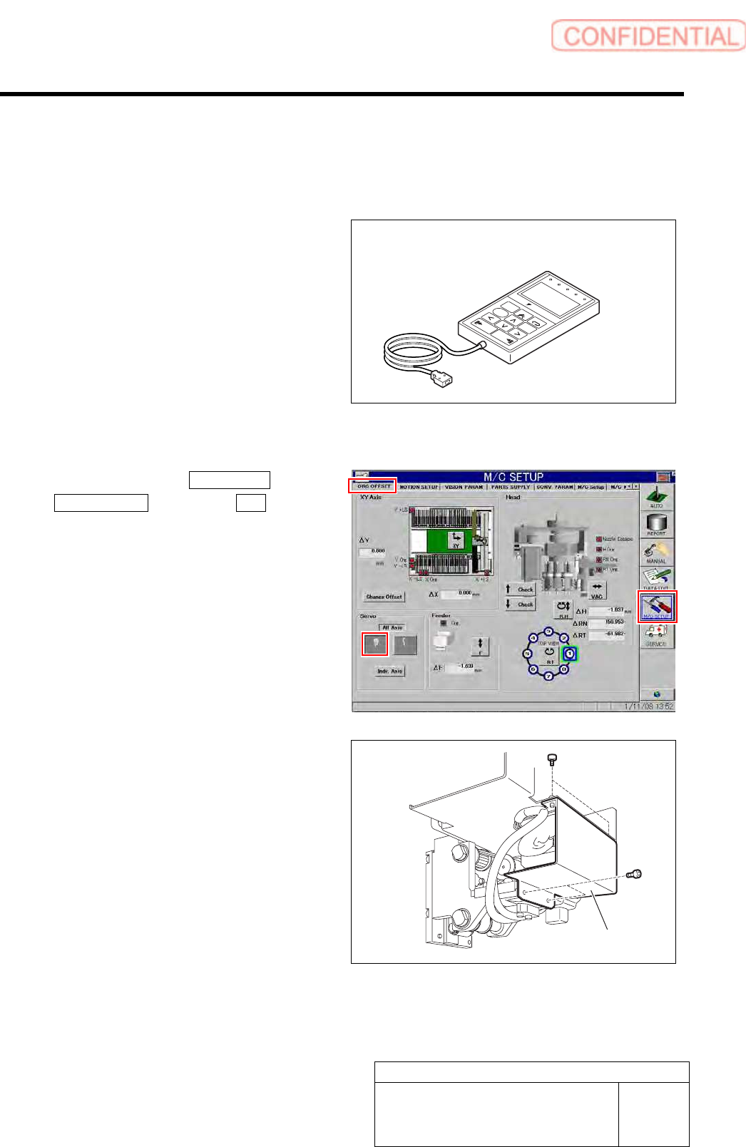
[Procedure]
1 Click in an order of M/C SETUP menu
ORG OFFSET tab Servo OFF button.
Servos for all axes are turned OFF.
2 Loosen the fixing bolts for the motor bracket
to free the motor from the belt.
1. Loosen the four screws to remove the F
axis cover.
Digital operator
F axis cover
Adjustment
HLGB-10406-01
FF/FR Axis Z-Phase Matching
SHEET
2/4
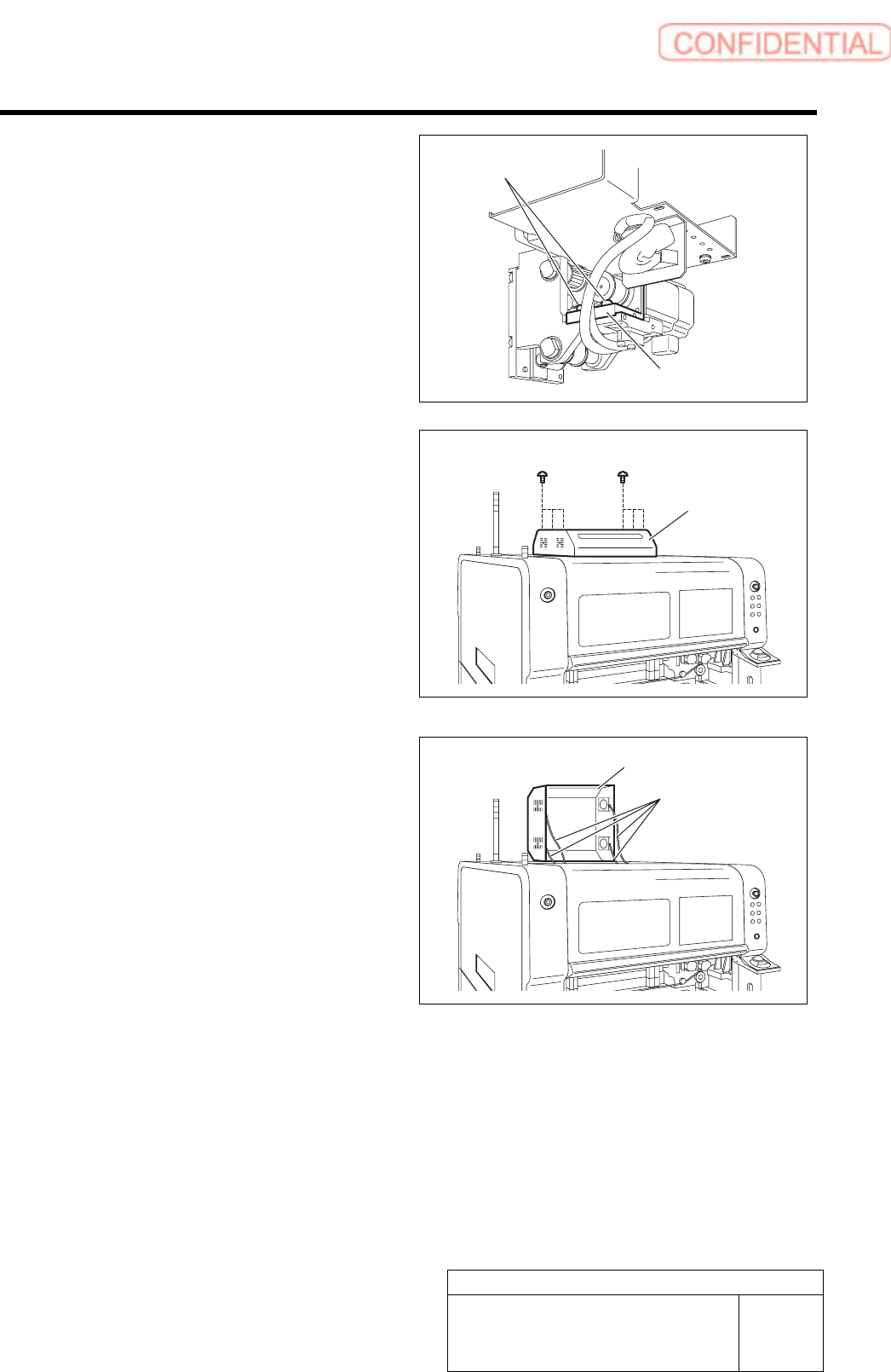
2. Loosen the two fixing screws for the
motor bracket.
3. Push the motor bracket to the back,
then the F axis belt is freed.
3 Remove the servo unit cover.
1. Loosen the six screws to raise the
servo unit cover.
2. Disconnect the FAN cable connected to
the servo unit cover.
3. Remove the servo unit cover.
Servo unit cover
FAN cable
Servo unit cover
Bracket
Fixing screw