MAN00000772_SI-G200BB_SVCPDFA.pdf - 第305页
Adjustment HLGB-10406-01 FF/FR A xis Z-Phase Matchin g SHEET 3/4 4 Connect the digital operat or to CN3 on the digital operat or . 5 Match Z phase of the F axis motor . 1. Press the MODE/SET key on the digital opera tor …
Adjustment
HLGB-10406-01
FF/FR Axis Z-Phase Matching
SHEET
2/4
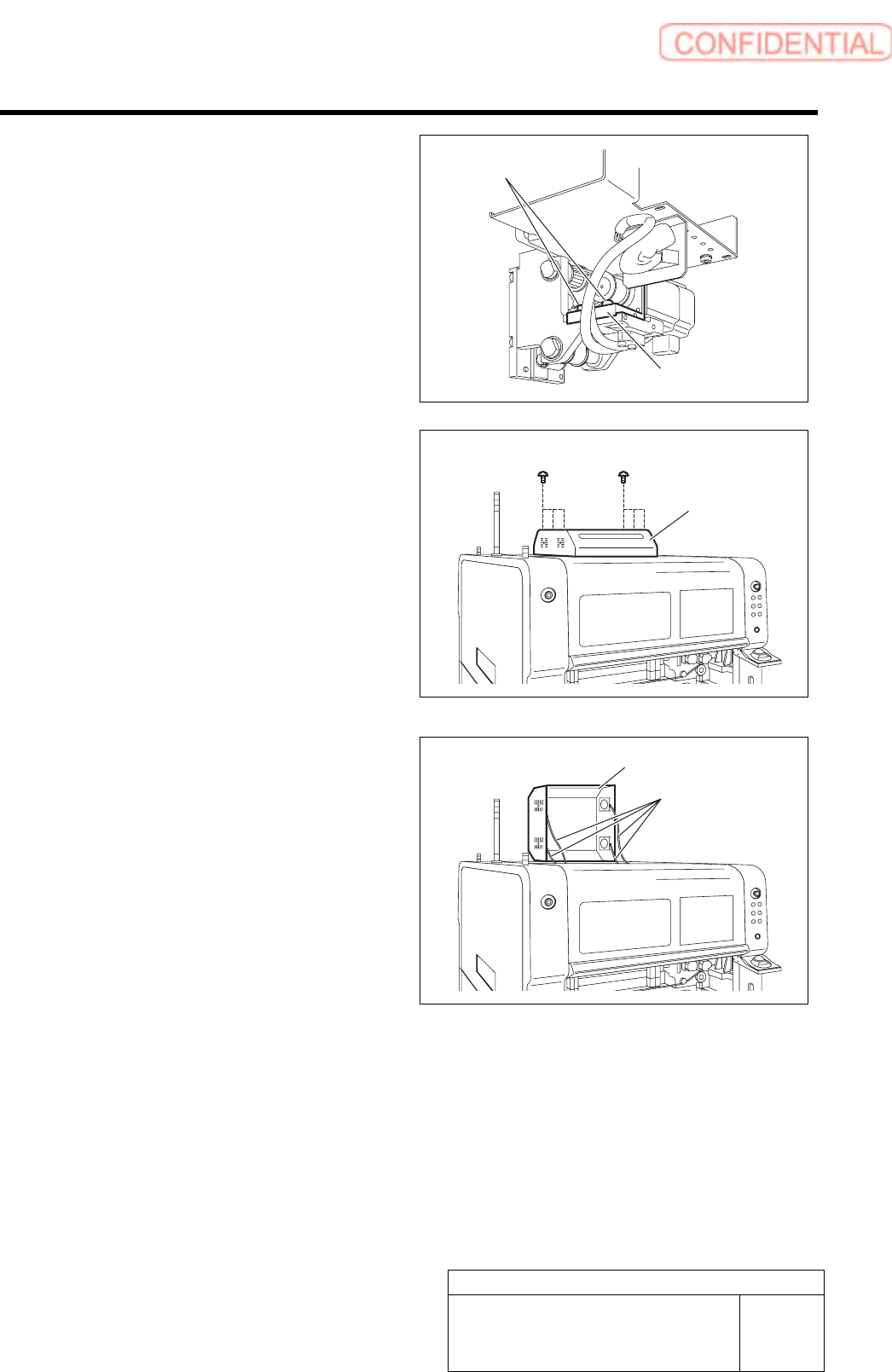
2. Loosen the two fixing screws for the
motor bracket.
3. Push the motor bracket to the back,
then the F axis belt is freed.
3 Remove the servo unit cover.
1. Loosen the six screws to raise the
servo unit cover.
2. Disconnect the FAN cable connected to
the servo unit cover.
3. Remove the servo unit cover.
Servo unit cover
FAN cable
Servo unit cover
Bracket
Fixing screw
Adjustment
HLGB-10406-01
FF/FR Axis Z-Phase Matching
SHEET
3/4
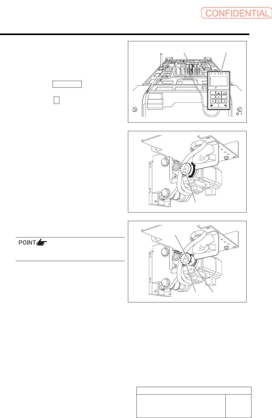
4 Connect the digital operator to CN3 on the
digital operator.
5 Match Z phase of the F axis motor.
1. Press the MODE/SET key on the
digital operator three times.
2. Press the ∧ key on the digital
operator three times.
- PRN / MON –
Un003 is displayed.
ALARM
RESET
SCROLL
YASKAWA
MODE/SET
JOG
SVON
READ
SERVO
DATA
WRITE
SERVO
SVCN TGON REF
CHARGE
COIN
VCMP
3. Turn the F axis motor pulley by one or
more turns to adjust the indication
(Un003=) on the digital operator to “0”.
Standard value :130000 ± 100
4. Put marking on the F axis belt and
pulley with white paint.
When marking, make sure that the pulley does
not rotate.
Digital operator F axis servo pack
Pulley
Pulley
Belt
Marking
Adjustment
HLGB-10406-01
FF/FR Axis Z-Phase Matching
SHEET
4/4
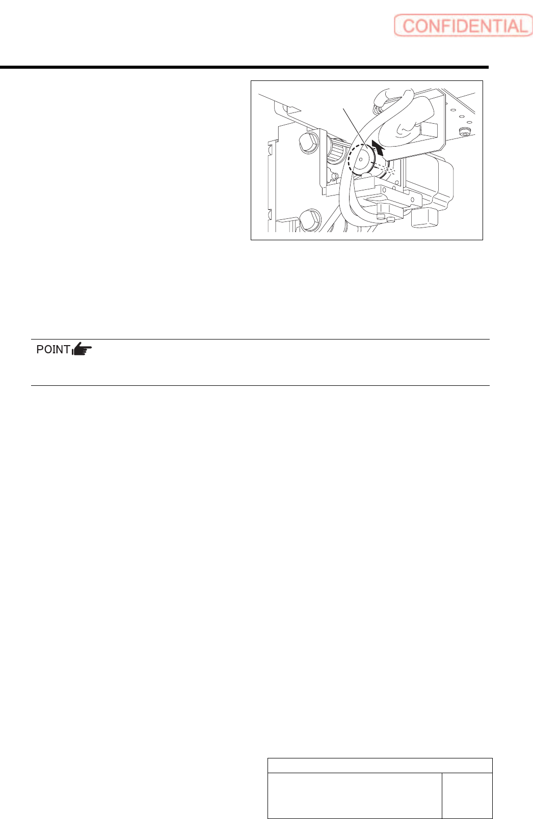
5. Rotate the pulley to shift the F axis
belt by one crest with the F axis belt
freed from the pulley.
6 Temporarily fasten the fixing screw with the
motor bracket pulled to the front.
7 Adjust tension for the F axis belt, then tighten the motor bracket fixing screws to the specified
torque.
Specified tightening torque: 196 cNm
For procedure of F axis belt tension adjustment, refer to the “FF/FR axis belt tension adjustment” on the
next page.
8 Remove the digital operator.
9 Install the F axis cover and the servo unit.
Pulley