MAN00000772_SI-G200BB_SVCPDFA.pdf - 第308页
Adjustment HLGB-10407-01 Adjustment of FF/FR A xis Belt T ension SHEET 2/2 3 Set the tension meter . WEIGHT =2.5 gf/m WIDTH =15 mm SP AN =40 mm For the detailed operating method of the tension meter , re fer to the manua…
Adjustment
HLGB-10407-01
Adjustment of FF/FR Axis Belt
Tension
SHEET
1/2
Adjustment of FF/FR Axis Belt Tension
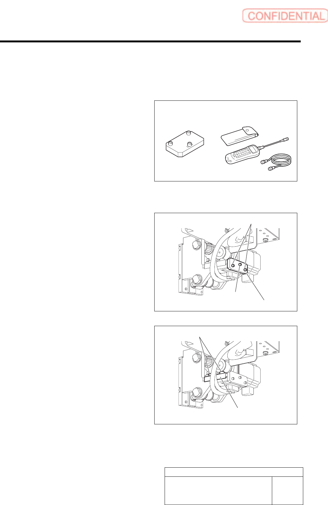
[Necessary jigs]
• Tension block Jig
• Tension meter
[Procedure]
1 Install the tension block jig to the feed body.
1. Fix the tension block jig to the feed
part body with two screws (2-M3).
2. Tighten the tension adjustment screw
and temporarily fasten to the motor
bracket.
2 Loosen the cap screws (2-M4) on the F axis
motor bracket.
Tension block jig Tension meter
Bracket
Tension block jig
Tension adjustment
screw
Cap screw
Cap screw
Adjustment
HLGB-10407-01
Adjustment of FF/FR Axis Belt
Tension
SHEET
2/2
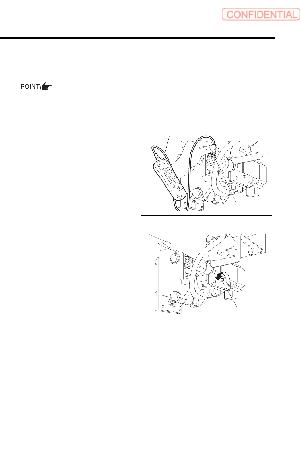
3 Set the tension meter.
WEIGHT =2.5 gf/m
WIDTH =15 mm
SPAN =40 mm
For the detailed operating method of the
tension meter, refer to the manual attached to
the tension meter.
4 Measure tension on the F axis belt.
1. Set the measuring terminal of tension
meter near the belt on the middle
between both pulleys.
2. When the belt is pulled by finger,
tension value of the belt is displayed
on the tension meter.
5 Adjust the belt tension by turning the tension
adjustment screw so that the value of the
tension measured in the procedure 4 is
within the standard.
Standard: 70 ~ 85 N
6 After adjusting the tension, retighten the cap screws (2-M4) on the F axis motor bracket to secure
the bracket.
7 Remove the tension block jig.
Tension adjustment screw
Tension meter
Belt
Adjustment
HLGB-10408-01
Adjustment of RTF/RTR Axis Belt
Tension
SHEET
1/2
Adjustment of RTF/RTR Axis Belt Tension
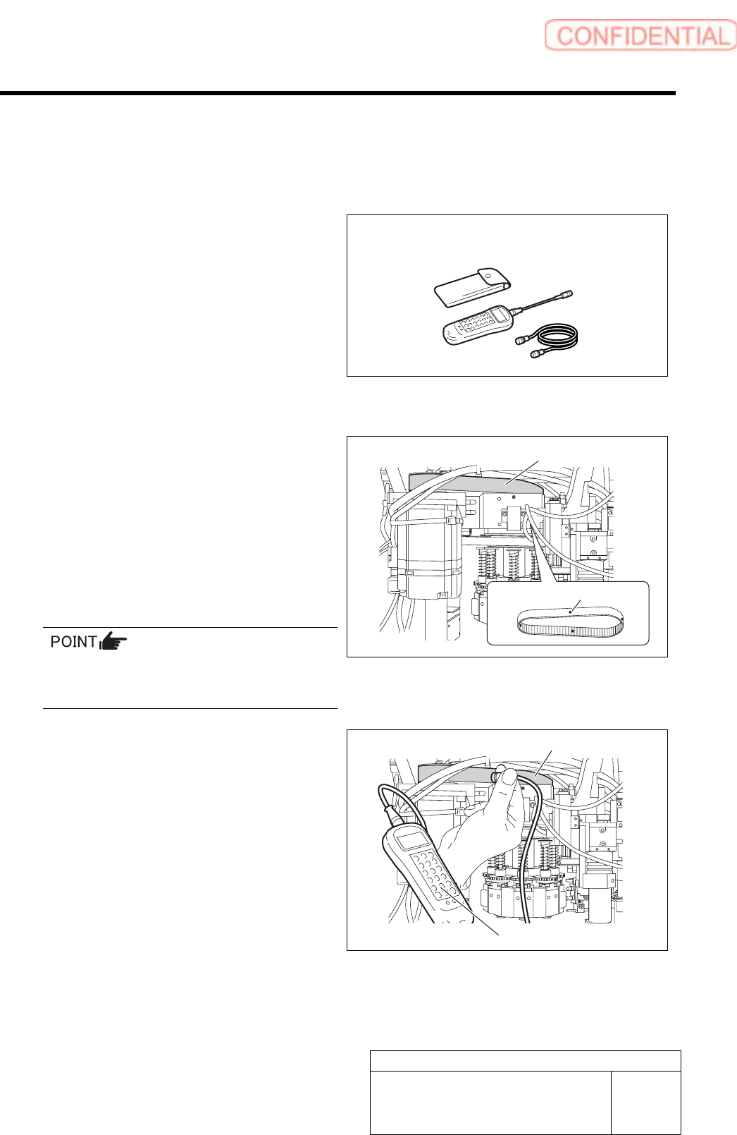
[Necessary jigs]
• Tension meter
[Preparation before work]
1 Put white marking on 4 locations on the RT
axis belt in the same interval from the front
of the unit.
2 Set the tension meter.
WEIGHT : 4.0 gf/m
WIDTH : 15 mm
SPAN : 95.0 mm
MIC GAIN : Turn up the volume to a position just
before the lamp lights up.
For the detailed operating method of the
tension meter, refer to the manual attached to
the tension meter.
3 Measure the tension on the white marked 4
locations on the RT axis.
1. Place the measuring terminal of the
tension meter on the center between
the both pulleys.
2. Knock the RN axis belt with finger,
then tension value on the belt is
displayed on the tension meter.
3. Measure the tension on the 4 measuring points on the RT axis belt, and check the value of
the tension.
Standard: 115 ± 5 N
Tension meter
Tension meter
RT axis belt
RT axis belt
White marking (4 locations)