MAN00000772_SI-G200BB_SVCPDFA.pdf - 第312页
Adjustment HLGB-10409-01 Adjustment of RNF/RNR Axis Belt T ension SHEET 2/2 4 If the tension of the RN axis belt is out of the standard, adj ust the tension. 1. Install the RN axis belt tensi on jig to the RN axis motor …
Adjustment
HLGB-10409-01
Adjustment of RNF/RNR Axis Belt
Tension
SHEET
1/2
Adjustment of RNF/RNR Axis Belt Tension
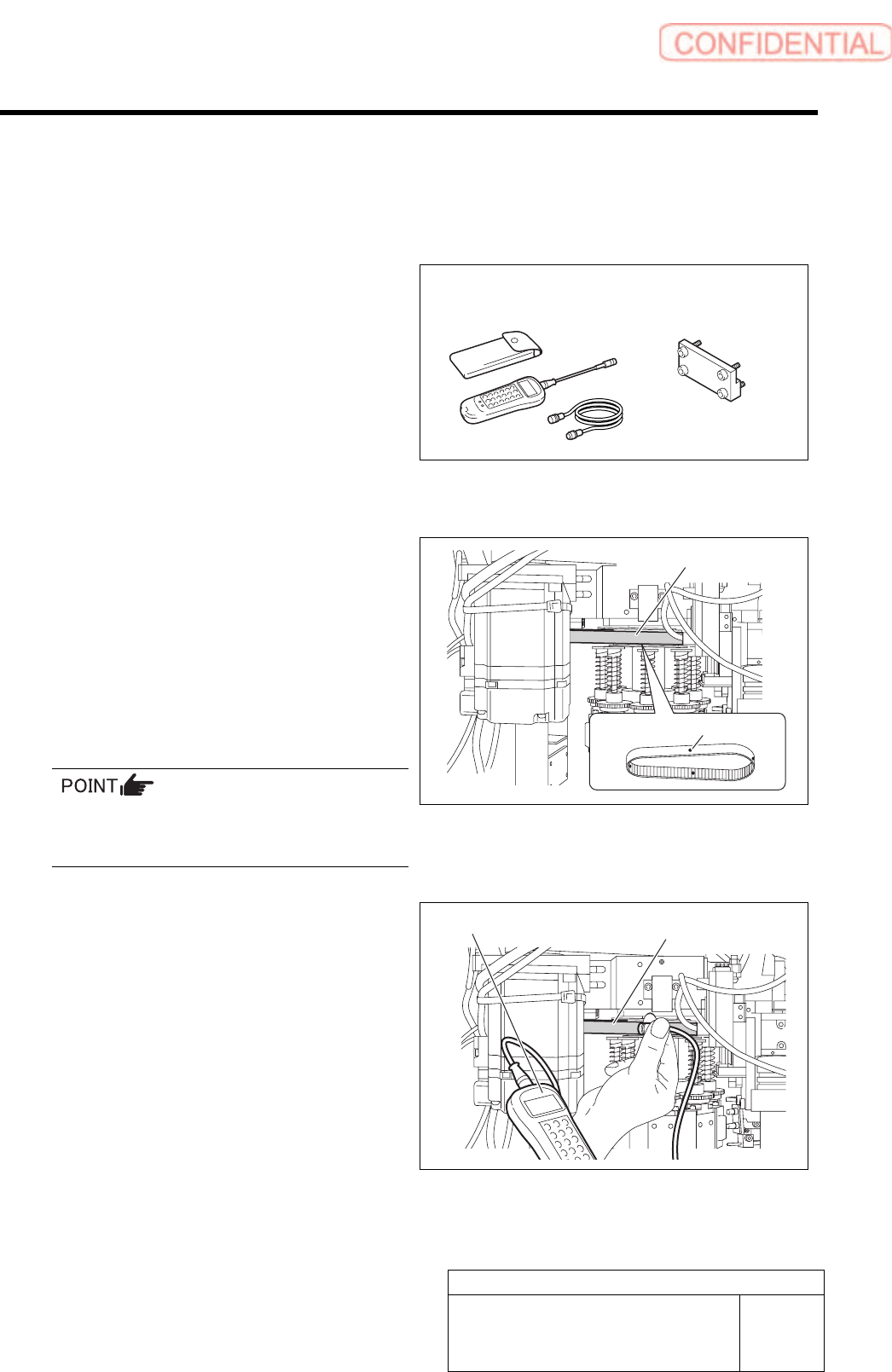
[Necessary jigs]
• Tension meter
• RN Axis belt tension Jig
[Preparation before work]
1 Put white marking on 4 locations on the RN
axis belt in the same interval from the front
of the unit.
2 Set the tension meter.
WEIGHT : 2.5 gf/m
WIDTH : 9 mm
SPAN : 96.0 mm
MIC GAIN : Turn up the volume to a position just
before the lamp lights up.
For the detailed operating method of the
tension meter, refer to the manual attached to
the tension meter.
3 Measure the tension on the white marked 4
locations on the RN axis.
1. Place the measuring terminal of the
tension meter on the center between
the both pulleys.
2. Knock the RN axis belt with finger,
then tension value on the belt is
displayed on the tension meter.
3. Measure the tension on the 4 measuring points on the RN axis belt.
Standard: 54 ±5 N
Tension meter
RN axis belt tension jig
Tension meter
RN axis belt
RN axis belt
White marking (4 locations)
Adjustment
HLGB-10409-01
Adjustment of RNF/RNR Axis Belt
Tension
SHEET
2/2
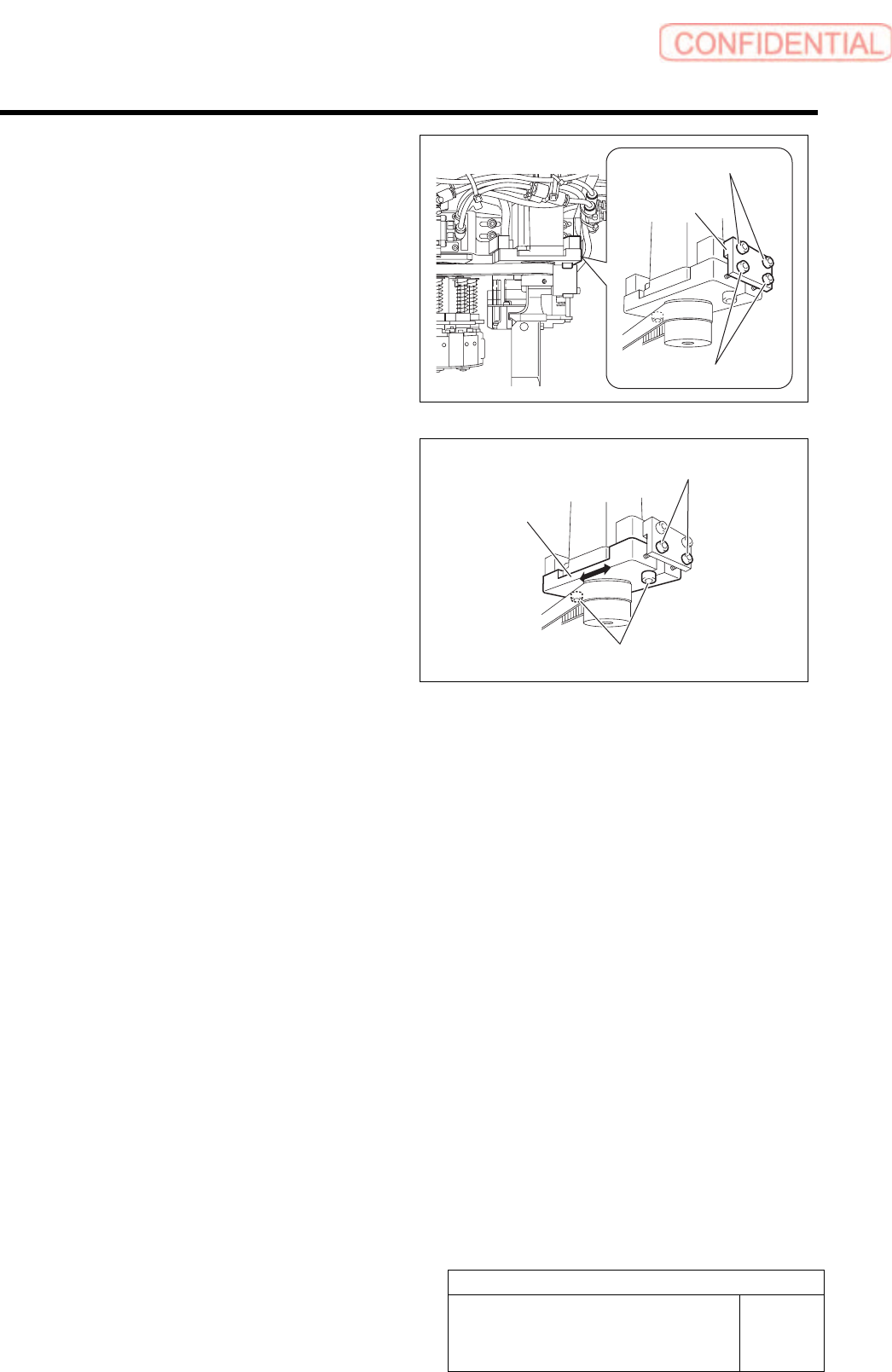
4 If the tension of the RN axis belt is out of the
standard, adjust the tension.
1. Install the RN axis belt tension jig to
the RN axis motor bracket with cap
screws (2).
2. Tighten the tension adjustment screw
into the motor bracket.
3. Loosen the RN axis motor bracket
mounting bolt.
4. Turn the tension adjustment screw for
the RN axis belt to adjust the belt
tension.
The belt is tensioned by turning the tension
adjustment screw clockwise, and the belt is
loosened by turning it counterclockwise.
5. Measure the tension on the 4 locations on the RN axis belt by using tension meter to check
that the tension is within the standard.
6. After adjusting the tension, fasten the RN axis motor mounting bolt with a torque of 441
cN・m.
7. Remove the RN axis belt tension jig.
RN axis belt
tension jig
Cap screw
Tension adjustment screw
Tension adjustment screw
Bracket
Mounting bolt
Adjustment
HLGB-10410-01
Gap Adjustment for Head Unit
Mechanical Valve and Plunger
SHEET
1/3
Gap Adjustment for Head Unit Mechanical Valve and Plunger
Perform this working on both heads on the front side and rear side.
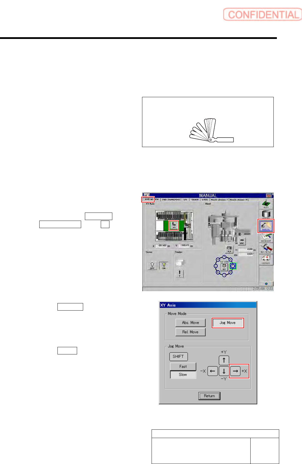
[Necessary jigs]
• Thickness gauge (t=1.5 mm)
[Preparation before work]
1 Perform origin position return of the unit.
1. Press the [ORG] button on the operation panel with the HI screen being displayed.
2 Manually move the head unit to a position of
the center on the left and right of the X axis.
1. Click in an order of MANUAL menu
AXIS MOTION tab XY button.
XY Axis screen is displayed.
2. Click the Jog Move button in the move
mode.
3. Press the right cursor key to jog move
the head unit to the center position on
the left and right.
4. Click the Return button to close the
XY Axis screen.
Thickness gauge