MAN00000772_SI-G200BB_SVCPDFA.pdf - 第314页
Adjustment HLGB-10410-01 Gap A djustment for Head Unit Mechanical V alve and Plunger SHEET 2/3 3 Press the emergency stop swit ch to turn off the servo. Because working has to be performed from the rear side of the head …
Adjustment
HLGB-10410-01
Gap Adjustment for Head Unit
Mechanical Valve and Plunger
SHEET
1/3
Gap Adjustment for Head Unit Mechanical Valve and Plunger
Perform this working on both heads on the front side and rear side.
[Necessary jigs]
• Thickness gauge (t=1.5 mm)
[Preparation before work]
1 Perform origin position return of the unit.
1. Press the [ORG] button on the operation panel with the HI screen being displayed.
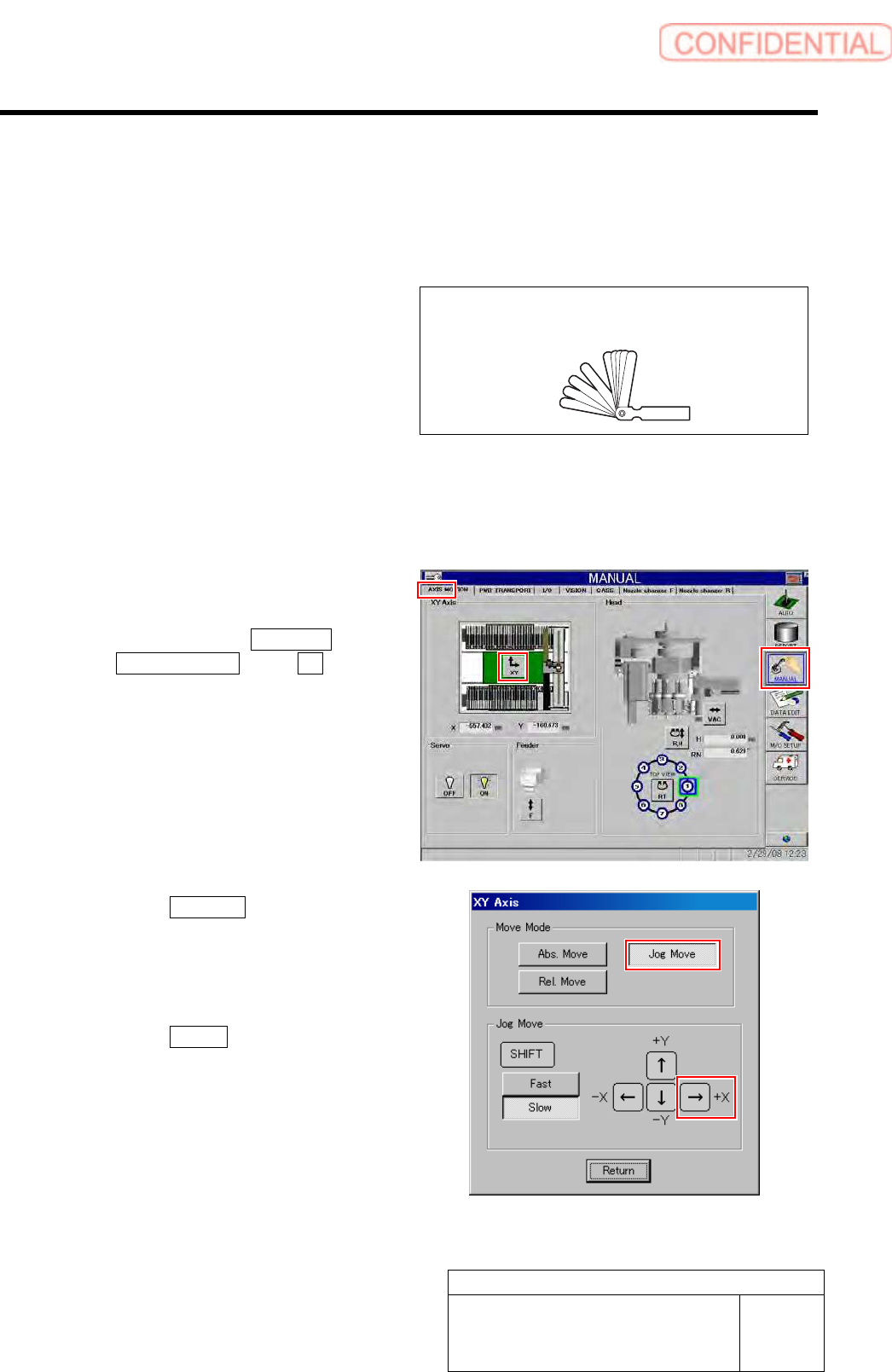
2 Manually move the head unit to a position of
the center on the left and right of the X axis.
1. Click in an order of MANUAL menu
AXIS MOTION tab XY button.
XY Axis screen is displayed.
2. Click the Jog Move button in the move
mode.
3. Press the right cursor key to jog move
the head unit to the center position on
the left and right.
4. Click the Return button to close the
XY Axis screen.
Thickness gauge
Adjustment
HLGB-10410-01
Gap Adjustment for Head Unit
Mechanical Valve and Plunger
SHEET
2/3
3 Press the emergency stop switch to turn off the servo.
Because working has to be performed from the rear side of the head part, work on the head on the front
side from the rear of the unit, and the head on the rear side from the front of the unit.
Press the emergency stop switch on the working side to turn OFF the servo in order to prevent the unit
from being operated mistakenly from opposite side of the unit without noticing that the other worker is
working.
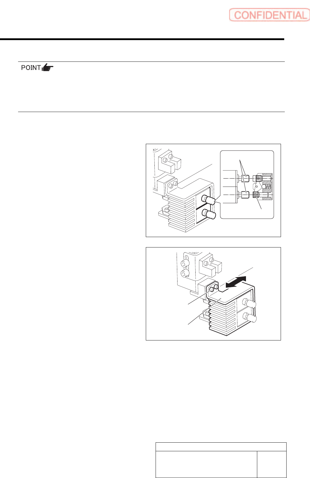
[Axis center adjuting procedure]
1 Visually check that axis center of the plunger
matches.
If the axis center matches, it is unnecessary to adjust,
however, be sure to retighten the mounting bracket.
If the axis center does not match, adjust the axis
center according to the following procedure.
2 Perform adjustment of axis centers of the
mechanical valve and plunger.
1. Loosen the cap screws (2 pcs, C3 x 6)
on the mounting bracket for plunger.
2. Move the bracket back and forth to
match the axis centers of the
mechanical valve and the plunger.
3. While matching the axis center in
height direction, fasten the cap screws
(2 pcs, C3 x 6) to fix the bracket.
Cap screw
Bracket
Plunger
Mechanical valve
Adjustment
HLGB-10410-01
Gap Adjustment for Head Unit
Mechanical Valve and Plunger
SHEET
3/3
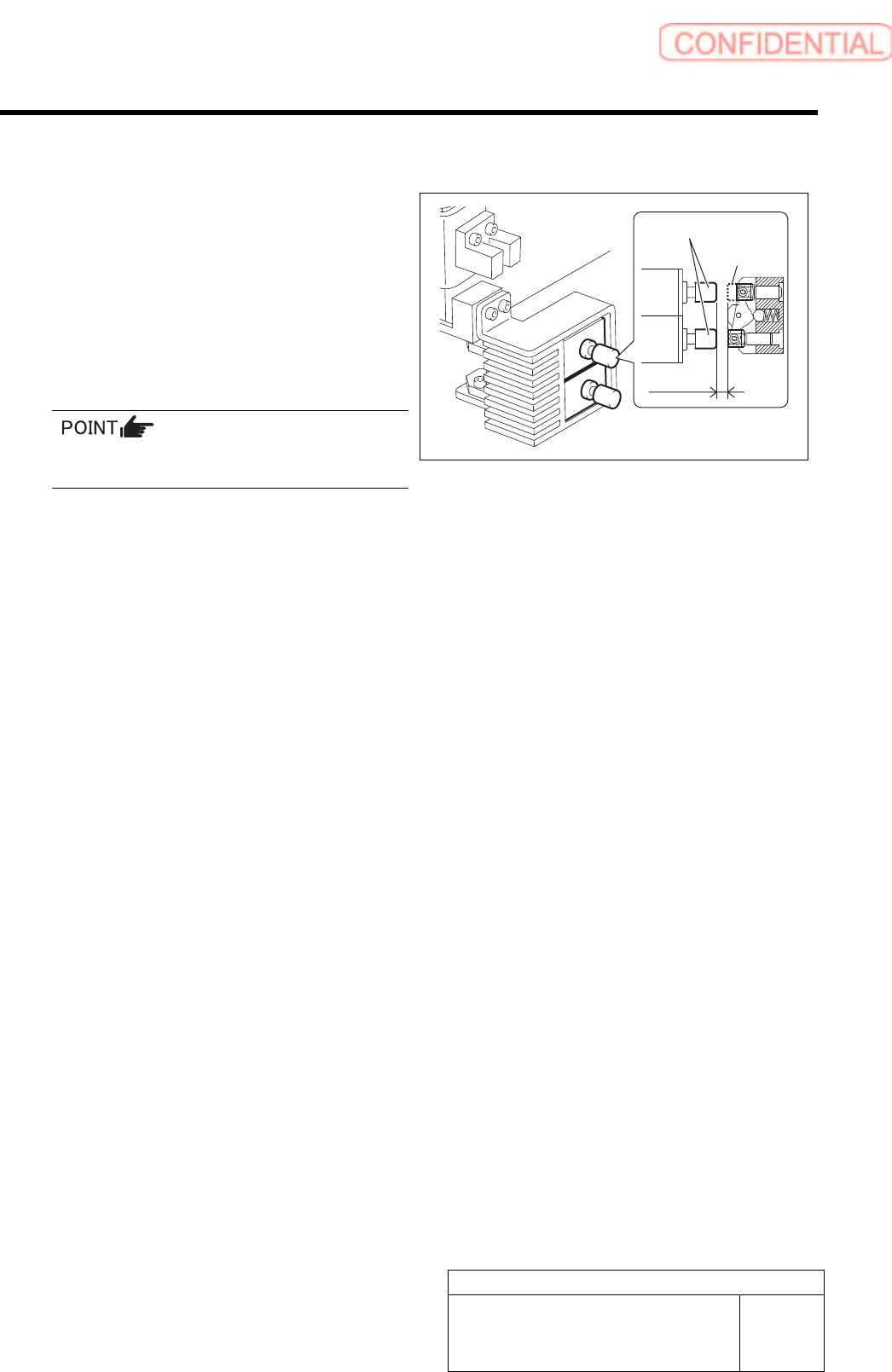
[Gap adjusting procedure]
1 Adjust the gap between the end of the
retracted plunger and the end of the
projected mechanical valve to 1.5 mm.
1. Loosen the cap screws (4 pcs, C3 x 5).
2. Adjust the gap between the end of the
retracted plunger and the end of the
projected mechanical valve to 1.5 mm
using a thickness gauge.
The mechanical valve and the plunger head
should be parallel to each other.
3. While matching the axis center in
height direction, fasten the cap screws
(4 pcs, C3 x 5) to fix the plunger.
Plunger
Mechanical
valve
1.5 mm