MAN00000772_SI-G200BB_SVCPDFA.pdf - 第317页
Adjustment HLGB-1041 1-01 Adjustment of Plunger Uppe r/Lower Backward Detect Sensor SHEET 2/2 4 Check the LED lighting-on st ate of the plunger return sensor (Upper/Lower). 1. Press in the mechanical valve. 2. Pull out t…
Adjustment
HLGB-10411-01
Adjustment of Plunger Upper/Lower
Backward Detect Sensor
SHEET
1/2
Adjustment of Plunger Upper/Lower Backward Detect Sensor
Perform this working on both heads on the front side and rear side.
[Necessary jigs]
• Thickness gauge
[Procedure]
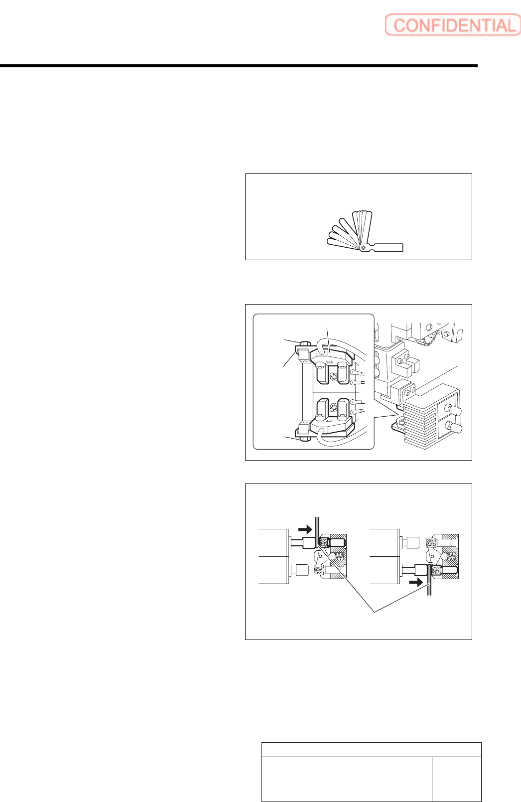
1 Loosen the bolts fastening the mounting
bracket for the plunger return sensor.
2 Adjust the LED extinguishing position of the
plunger return sensor (Upper/Lower).
1. Press in the mechanical valve.
2. Pull out the plunger by hand, and
pinch a thickness gauge of t=1.0 mm
between the plunger and mechanical
valve.
3. Move the bracket to adjust the sensor
position so that the LED for the
plunger return sensor extinguishes in
this state.
3 Fasten the bolts for the mounting bracket to fix the plunger return sensor.
Thickness gauge
Bolt
Bracket
Upper Lower
Thickness gauge
Plunger return sensor
Bolt
Adjustment
HLGB-10411-01
Adjustment of Plunger Upper/Lower
Backward Detect Sensor
SHEET
2/2
4 Check the LED lighting-on state of the plunger return sensor (Upper/Lower).
1. Press in the mechanical valve.
2. Pull out the plunger by hand, and pinch a thickness gauge of t=1.2 mm between the
plunger and the mechanical valve.
3. Check that the LED for the plunger return sensor lights up in this state.
<Thickness of thickness gauge and state of sensor LED>
Thickness of thickness gauge State of LED for plunger return
sensor
1.0 mm Extinguish
1.2 mm Lights-up
Non (Origin position) Lights-up
Adjustment
HLGB-10412-01
Nozzle Height Adjustment
SHEET
1/3
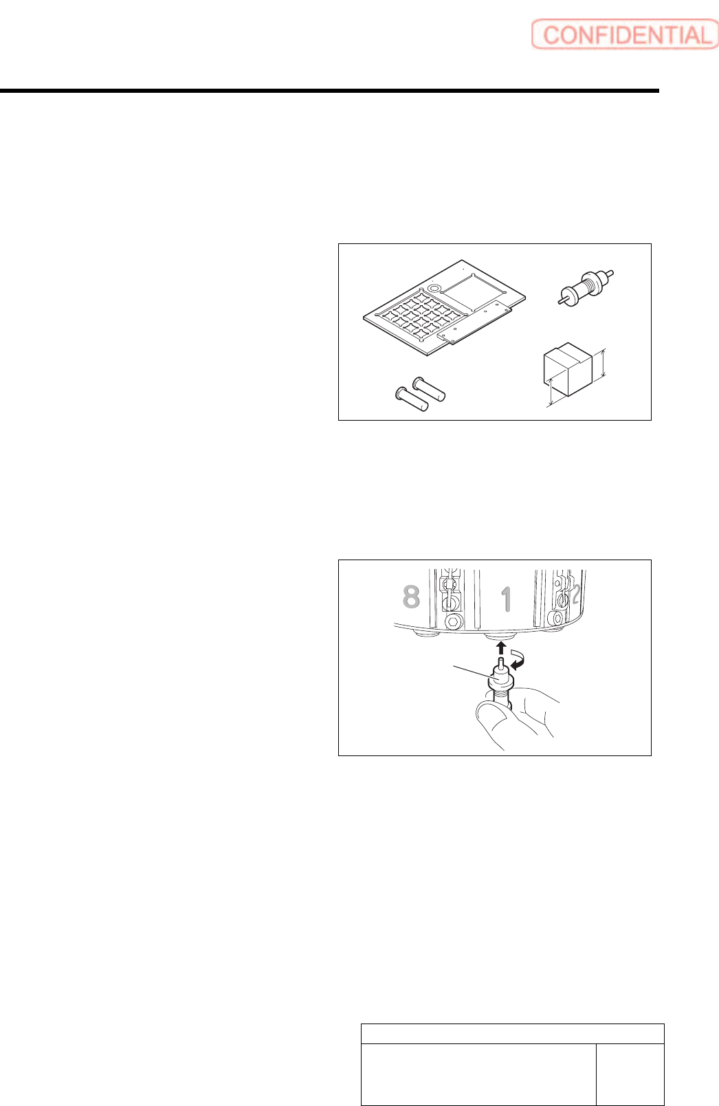
Nozzle Height Adjustment
Perform this working on both heads on the front side and rear side.
[Necessary jigs]
A Calibration plate jig
B Jig positioning pin
C Length reference nozzle jig
D Nozzle height adjusting block
23.1mm
22.9mm
[Procedure]
1 Install the calibration plate jig.
For calibration plate installation procedure, procedure, refer to the “Install the Calibration Plate Jig [HLGB-10101-01]”.
2 Move the heat to a position where working
can be easily performed, and install the
length reference jig nozzle to the turret No.1.
A
C
B
D
Length reference
nozzle
j
i
g