MAN00000772_SI-G200BB_SVCPDFA.pdf - 第318页
Adjustment HLGB-10412-01 Nozzle Height A djustment SHEET 1/3 Nozzle Height Adjustment Perform this working on both heads on the front sid e and rear side. [Necessary jigs] A Calibration plate jig B Jig positioning pin C …
Adjustment
HLGB-10411-01
Adjustment of Plunger Upper/Lower
Backward Detect Sensor
SHEET
2/2
4 Check the LED lighting-on state of the plunger return sensor (Upper/Lower).
1. Press in the mechanical valve.
2. Pull out the plunger by hand, and pinch a thickness gauge of t=1.2 mm between the
plunger and the mechanical valve.
3. Check that the LED for the plunger return sensor lights up in this state.
<Thickness of thickness gauge and state of sensor LED>
Thickness of thickness gauge State of LED for plunger return
sensor
1.0 mm Extinguish
1.2 mm Lights-up
Non (Origin position) Lights-up
Adjustment
HLGB-10412-01
Nozzle Height Adjustment
SHEET
1/3
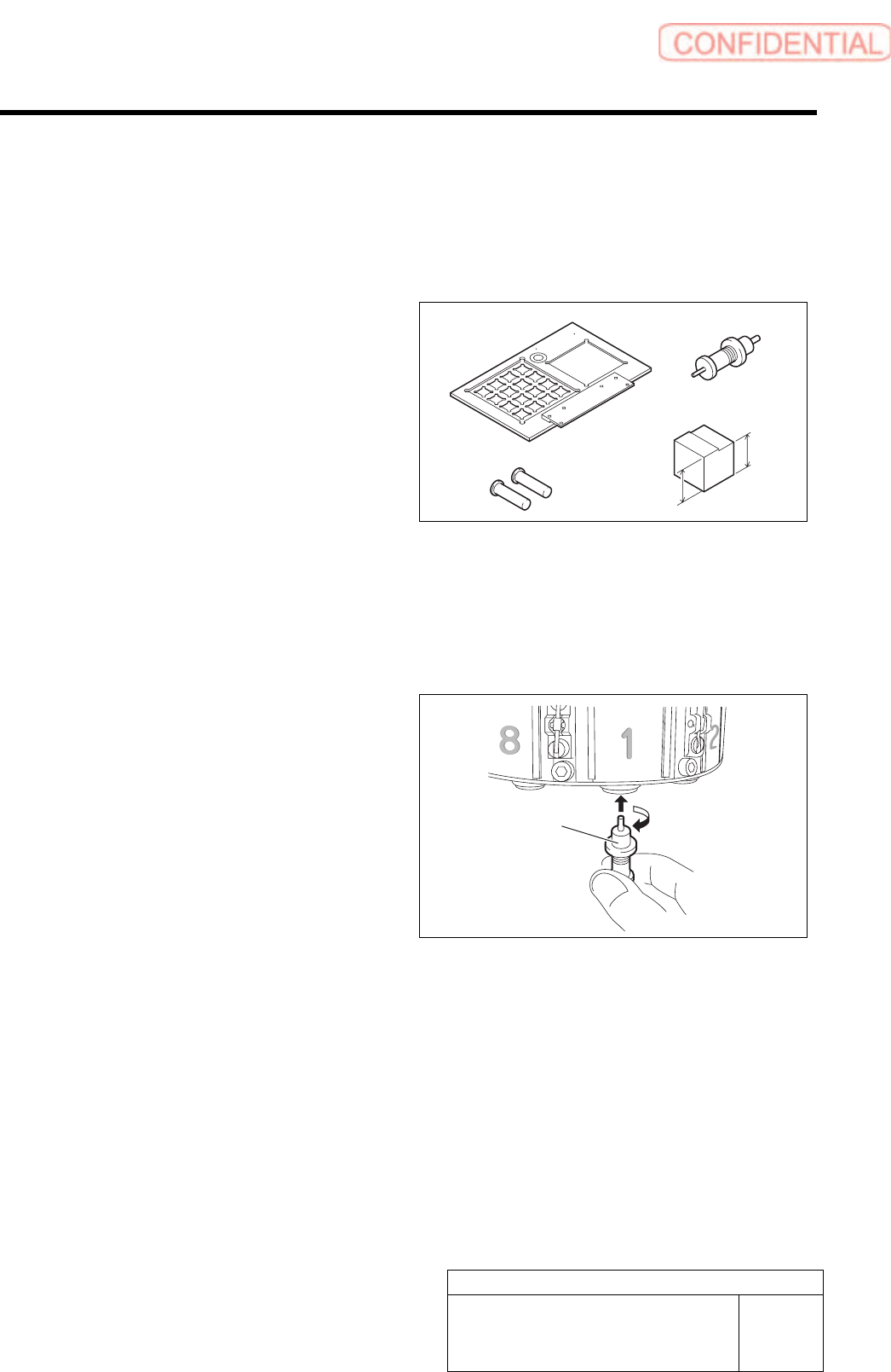
Nozzle Height Adjustment
Perform this working on both heads on the front side and rear side.
[Necessary jigs]
A Calibration plate jig
B Jig positioning pin
C Length reference nozzle jig
D Nozzle height adjusting block
23.1mm
22.9mm
[Procedure]
1 Install the calibration plate jig.
For calibration plate installation procedure, procedure, refer to the “Install the Calibration Plate Jig [HLGB-10101-01]”.
2 Move the heat to a position where working
can be easily performed, and install the
length reference jig nozzle to the turret No.1.
A
C
B
D
Length reference
nozzle
j
i
g
Adjustment
HLGB-10412-01
Nozzle Height Adjustment
SHEET
2/3
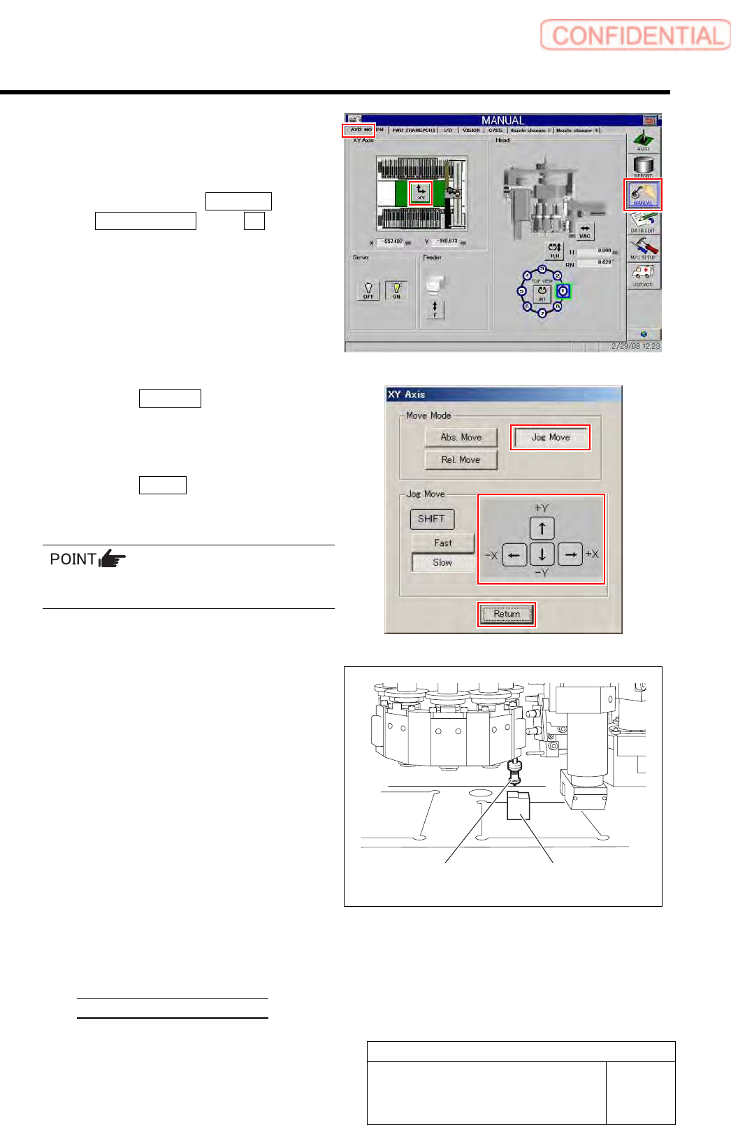
3 Move the length reference jig nozzle to
proximity of the center of the calibration
plate.
1. Click in an order of MANUAL menu
AXIS MOTION tab XY button.
XY Axis screen is displayed.
2. Click the Jog Move button.
3. Press the cursor key to jog-move the
reference jig nozzle to vicinity of center
of the calibration plate.
4. Click the Return button to close XY
axes screen.
If the Shift key on the keyboard is pressed,
Fast/Slow for Jog Move can be switched.
4 Check difference in height between the
calibration plate and the length reference jig
nozzle with a nozzle height adjusting block.
1. Place a head height adjusting block
under the reference jig nozzle.
2. Check that lower face of the head
height adjusting block is inserted
between the calibration plate and
reference jig nozzle.
3. Check that higher face of the head
height adjusting block is not inserted
between the calibration plate and
reference jig nozzle.
Level difference is high 23.1[mm]
Level difference is low 22.9[mm]
Length reference
nozzle jig
Nozzle height
adjusting block