MAN00000772_SI-G200BB_SVCPDFA.pdf - 第320页
Adjustment HLGB-10412-01 Nozzle Height A djustment SHEET 3/3 5 If clearance between the calibration plat e and reference jig nozzle exceed s 23.1mm, adjust the height by the following procedure. 1. Slightly loosen th e b…
Adjustment
HLGB-10412-01
Nozzle Height Adjustment
SHEET
2/3
3 Move the length reference jig nozzle to
proximity of the center of the calibration
plate.
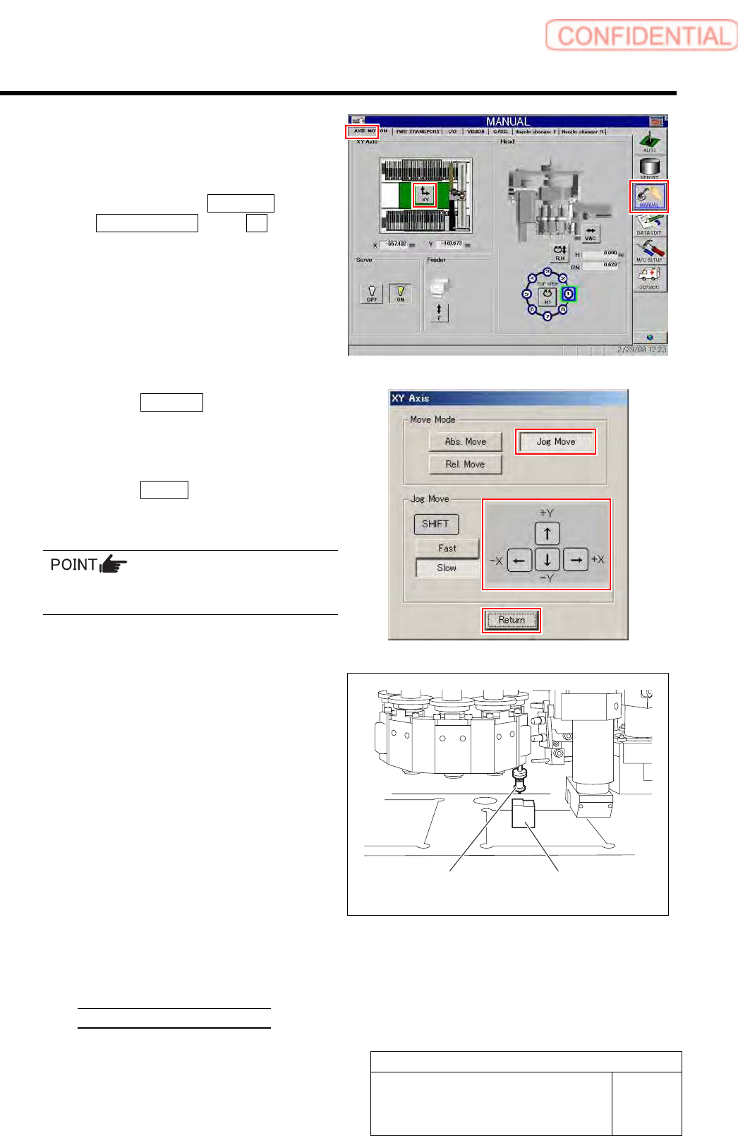
1. Click in an order of MANUAL menu
AXIS MOTION tab XY button.
XY Axis screen is displayed.
2. Click the Jog Move button.
3. Press the cursor key to jog-move the
reference jig nozzle to vicinity of center
of the calibration plate.
4. Click the Return button to close XY
axes screen.
If the Shift key on the keyboard is pressed,
Fast/Slow for Jog Move can be switched.
4 Check difference in height between the
calibration plate and the length reference jig
nozzle with a nozzle height adjusting block.
1. Place a head height adjusting block
under the reference jig nozzle.
2. Check that lower face of the head
height adjusting block is inserted
between the calibration plate and
reference jig nozzle.
3. Check that higher face of the head
height adjusting block is not inserted
between the calibration plate and
reference jig nozzle.
Level difference is high 23.1[mm]
Level difference is low 22.9[mm]
Length reference
nozzle jig
Nozzle height
adjusting block
Adjustment
HLGB-10412-01
Nozzle Height Adjustment
SHEET
3/3
5 If clearance between the calibration plate
and reference jig nozzle exceeds 23.1mm,
adjust the height by the following procedure.
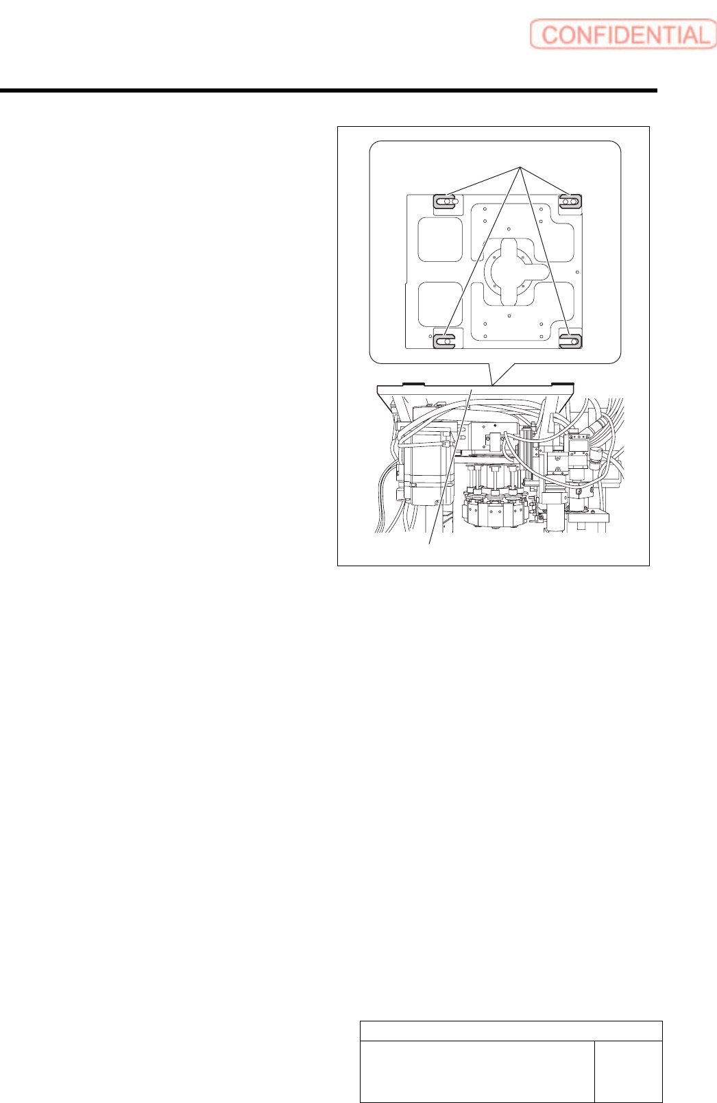
1. Slightly loosen the bolts fixing the B
head housing.
2. Insert a height adjusting spacer into
the gap above the B head housing.
3. Tighten the bolts on the B head
housing, and check clearance between
the calibration plate and reference jig
again.
Repeat the procedure 5 to 6 until clearance
between the calibration plate and reference jig
nozzle falls in a rage from 22.9 to 23.1mm.
Spacer
B Head housing
Adjustment
HLGB-10413-01
Nozzle Escape Detect Sensor
Position Adjustment
SHEET
1/5
Nozzle Escape Detect Sensor Position Adjustment
Perform this working on both heads on the front side and rear side.
[Necessary jigs]
• Nozzle (used in production)
• Thickness gauge
[Procedure]
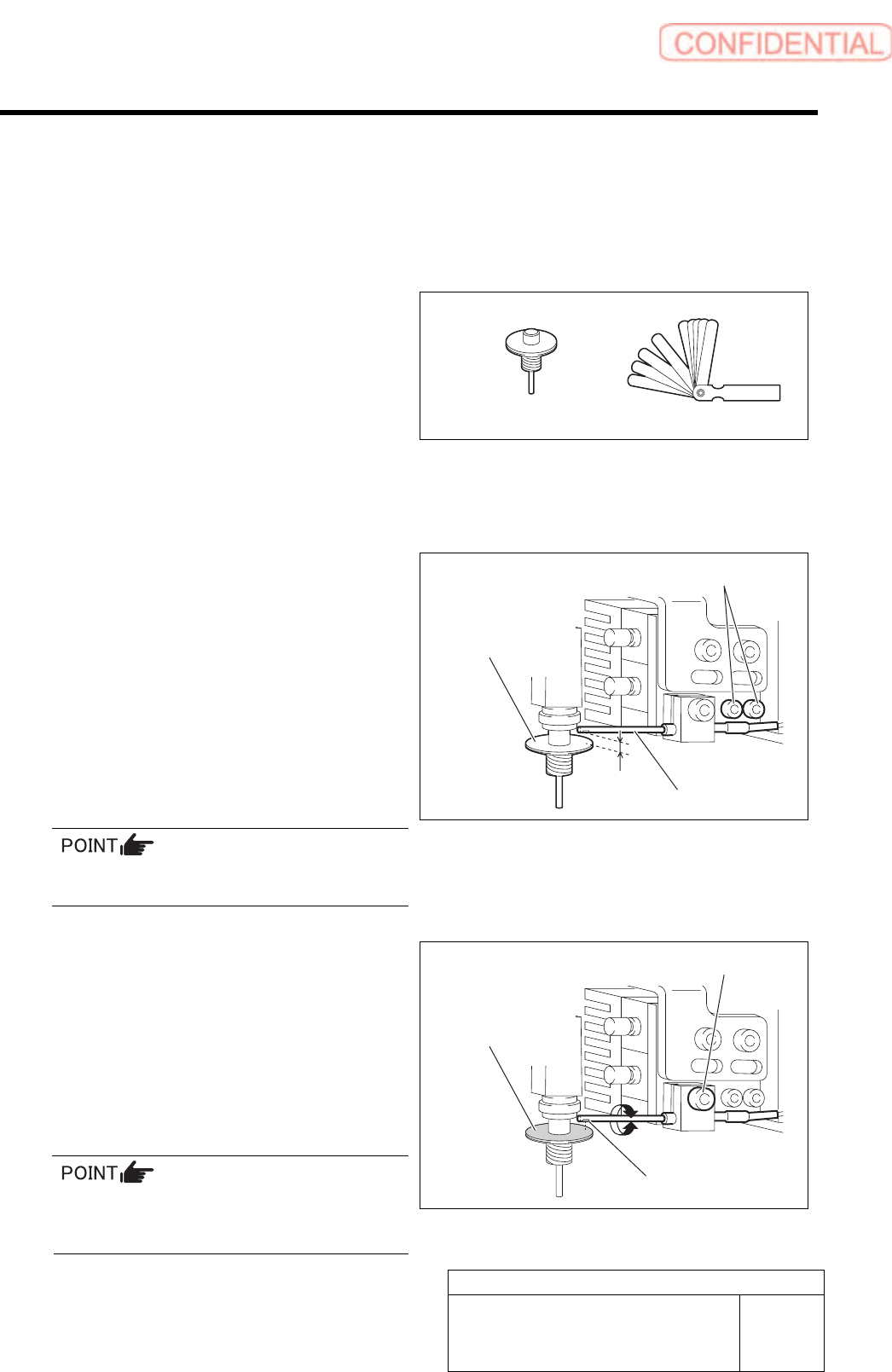
1 Install a nozzle for production to the turret No.1.
2 Adjust the clearance between the nozzle
omission detection sensor and the upper
face of the nozzle reflector to 1.0 mm.
1. Loosen the cap screw for the nozzle
omission detection sensor.
2.
Adjust with thickness gauge so that
clearance between the end of the nozzle
omission detection sensor and the
upper face of the reflector is 1.0 mm.
3. Tighten the cap screw.
Fiber sensor is used in the nozzle omission
detection sensor.
3 Adjust the optical axis of the nozzle
omission detection sensor.
1. Loosen the split fastening screw fixing
the nozzle omission detection sensor.
2. Turn the nozzle omission detection
sensor to adjust so that the sensor
luminescence part is directed to
reflector plane of the nozzle.
Optical axis can be easily adjusted by slightly
widening the split fastening part of the bracket
using flat end screwdriver.
Nozzle
(used in production)
Cap screw
Nozzle omission
detection sensor
1.0 mm
Nozzle
Reflector plane part
Split fastening screw
Sensor luminescence part
Thickness gauge