MAN00000772_SI-G200BB_SVCPDFA.pdf - 第323页
Adjustment HLGB-10413-01 Nozzle Escape Detect Sens or Position Adjus tment SHEET 3/5 5. Set the “2. T imer function” to “------ (timer ineffe ctive)” and press the MODE button. Changes to the “3. MODE key setting” displa…
Adjustment
HLGB-10413-01
Nozzle Escape Detect Sensor
Position Adjustment
SHEET
2/5
3. Tighten the split fastening screw.
4. Rotate the nozzle by one turn, and
check that laser from light emitting
section is emitted to the reflector plane
at every angle.
5. Check that there’s some clearance
between the end of the nozzle omission
detection sensor and the nozzle O-ring
spring.
Check clearance at the ceramic ball section.
4 Set the nozzle omission detection sensor
amplifier mounted on the side of the head.
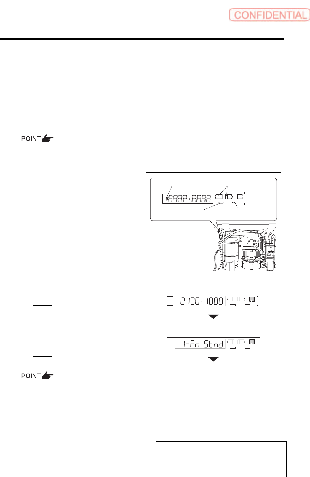
1. Open the cover of the sensor amplifier.
2. Turn the SET/RUN selector switch to
the “SET” side.
“Teaching” window appears, and present light
receiving value/threshold value are displayed.
3. On “Teaching” display, press the
MODE button to change the display
without doing anything.
Changes to the “1. Detecting function”.
4. Set the “1. Detecting function” to the
“Std (standard setting)” and press the
MODE button.
Changes to the “2. Timer function” display.
To change the selecting items on each set
display, press the UP / DOWN button.
UP/DOWN button
MODE
button
SET/RUN selector switch
Operation mode
selector switch
MODE button
MODE button
ON/OFF display part
Adjustment
HLGB-10413-01
Nozzle Escape Detect Sensor
Position Adjustment
SHEET
3/5
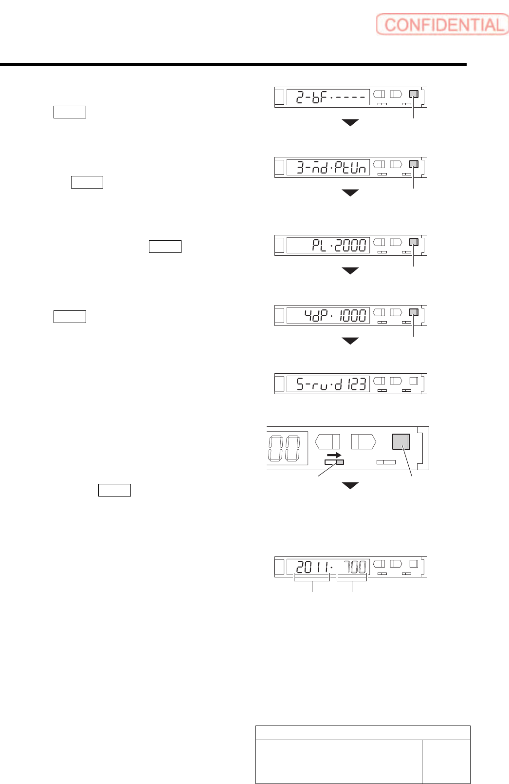
5. Set the “2. Timer function” to “------
(timer ineffective)” and press the
MODE button.
Changes to the “3. MODE key setting” display.
6. Set the “3. MODE key setting” to
“(Power tuning execution)” and press
the MODE button.
Changes to the “Power tuning target value”
display.
7. Set the “Power tuning target value” to
“2000” and press the MODE button.
Changes to the “4. Display change” display.
8. On the “4. Display change”, press the
MODE button without doing
anything.
Changes to the “5. Display direction” display.
9. Set the “5. Display direction” to “D123
(normal setting)”.
5 Set sensitivity of the nozzle omission
detection sensor.
1. Turn the SET/RUN selector switch to
the “RUN” side.
2. Press the MODE button for longer
than 3 seconds.
Light receiving value/threshold is automatically
adjusted.
L
SET RUN
UP DOWN MODE
D
3. Check the light receiving value.
If the light receiving value is within a range of
“2000±100”, setting is completed.
If the light receiving value is out of a range of
“2000±100”, re-perform the positional
adjustment of the nozzle omission detection
sensor performed in the procedures 2 and 3.
MODE button
MODE button
MODE button
SET/RUN selector switch
MODE button
Light receiving value Threshold
MODE button
Adjustment
HLGB-10413-01
Nozzle Escape Detect Sensor
Position Adjustment
SHEET
4/5
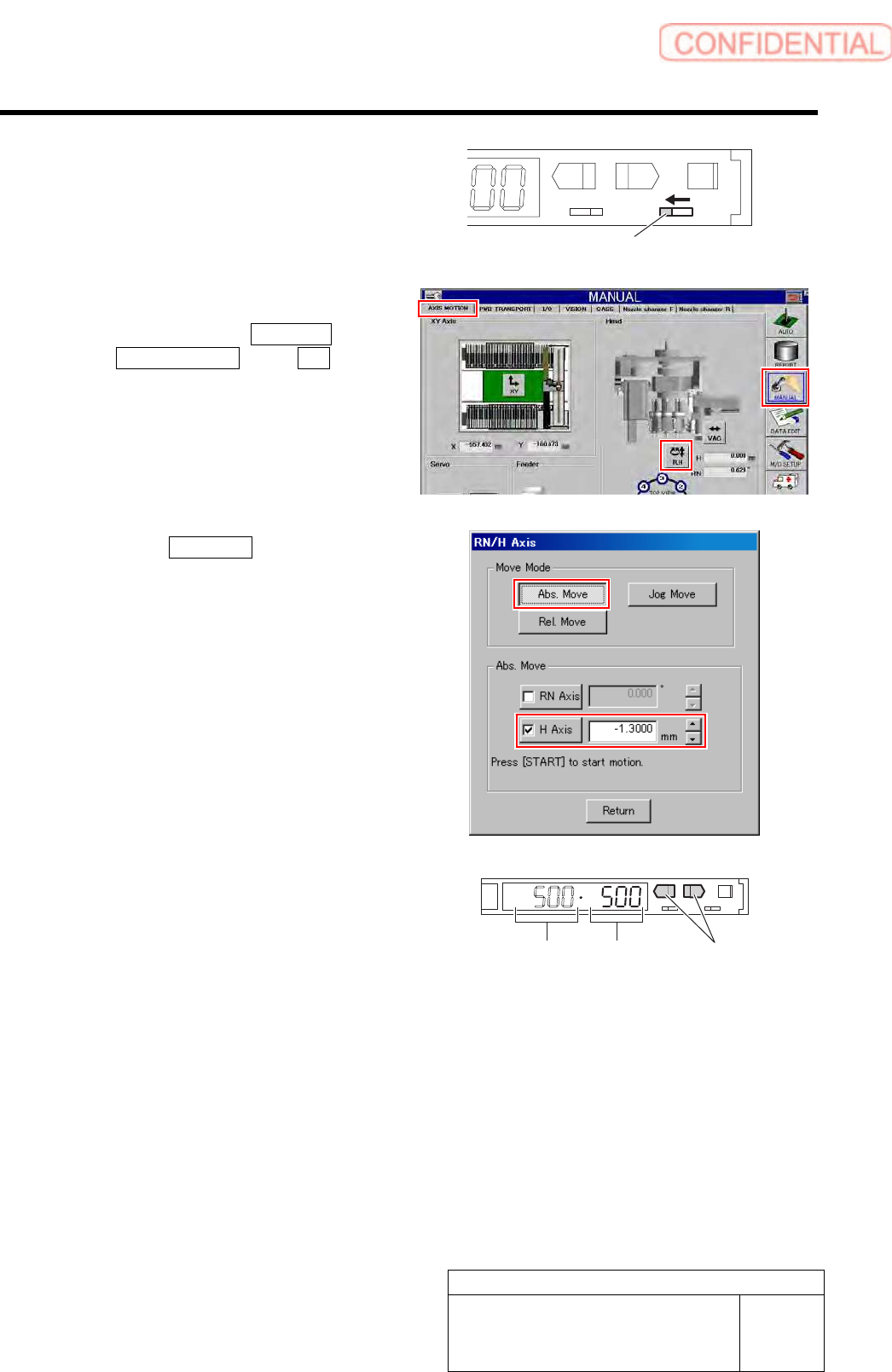
6 Change over the operation mode selector
switch to the “L” side to light up the lamp.
L
SET RUN
UP DOWN MODE
D
7 Set the threshold.
1. Click in an order of MANUAL menu
AXIS MOTION tab R.H button.
RN/H Axis screen is displayed.
2. Click the Abs. Move button.
3. Click the check box for H axis and put
check in it to input “-1.3”.
4. Press the [START] button on the
operation panel.
H axis lowers to a position of -1.3 mm.
5. Check the present light receiving
value with the nozzle omission
detection sensor amplifier, and set its
value to the threshold.
Example: If the light receiving value is “500”, set
the threshold to “500”.
Light receiving value = Threshold
UP/DOWN button
Operation mode selector switch