MAN00000772_SI-G200BB_SVCPDFA.pdf - 第325页
Adjustment HLGB-10413-01 Nozzle Escape Detect Sens or Position Adjus tment SHEET 5/5 8 Check that the sensor is turned of f at a position where H axis is lowered by -1.5 mm. 1. On the RN/H Axis screen, click check box fo…
Adjustment
HLGB-10413-01
Nozzle Escape Detect Sensor
Position Adjustment
SHEET
4/5
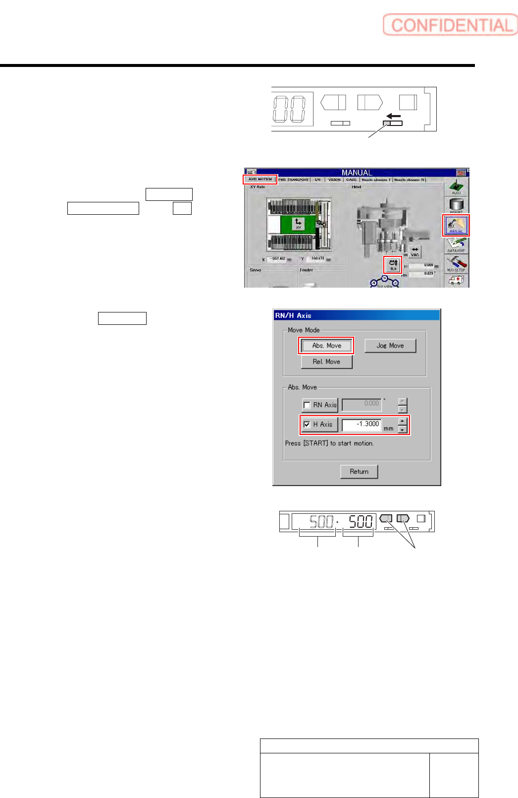
6 Change over the operation mode selector
switch to the “L” side to light up the lamp.
L
SET RUN
UP DOWN MODE
D
7 Set the threshold.
1. Click in an order of MANUAL menu
AXIS MOTION tab R.H button.
RN/H Axis screen is displayed.
2. Click the Abs. Move button.
3. Click the check box for H axis and put
check in it to input “-1.3”.
4. Press the [START] button on the
operation panel.
H axis lowers to a position of -1.3 mm.
5. Check the present light receiving
value with the nozzle omission
detection sensor amplifier, and set its
value to the threshold.
Example: If the light receiving value is “500”, set
the threshold to “500”.
Light receiving value = Threshold
UP/DOWN button
Operation mode selector switch
Adjustment
HLGB-10413-01
Nozzle Escape Detect Sensor
Position Adjustment
SHEET
5/5
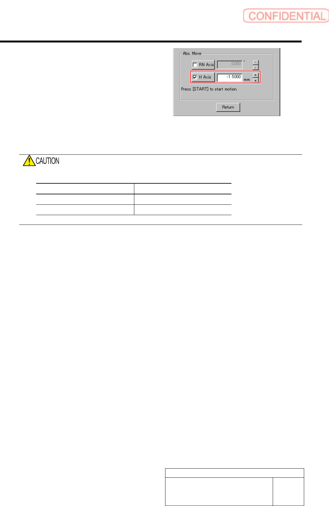
8 Check that the sensor is turned off at a
position where H axis is lowered by -1.5 mm.
1. On the RN/H Axis screen, click check
box for H axis and put check in it to
input “-1.5”.
2. Press the [START] button on the
operation panel.
H axis lowers to a position of -1.5 mm.
3. Check that the sensor is turned off.
Do not confuse the lowering dimension when checking sensor OFF and the lowering dimension for
setting threshold.
Item H Axis lowering dimension
Threshold setting -1.3 mm
Sensor OFF check -1.5 mm
9 This is the end of setting of the nozzle omission detection sensor.
1. Close the cover for the nozzle omission detection sensor amplifier.
2. Remove the nozzle for production installed on the head.
Adjustment
HLGB-10414-01
Phase Adjustment for Nozzle
SHEET
1/7
Phase Adjustment for Nozzle
Perform this working on both heads on the front side and rear side.
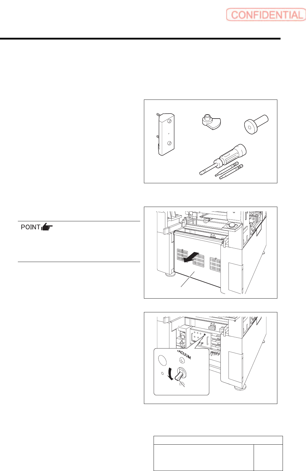
[Necessary jigs]
A Phase adjusting jig (1)
B Phase adjusting jig (2)
C Pull-out jig
D Torque driver (15[cN・m]~40[cN・m])
[Procedure]
1 Turn off the VACUUM breaker.
Turn OFF the VACUUM breaker before
removing the mechanical valve in order to
prevent suction of contaminant and dust from
the mechanical valve.
1. Loosen the screws (2-+T4×8) to
remove the lower cover on the back of
the unit.
2. Turn off the VACUUM breaker on the
power unit part.
Lower cover
VACUUM breaker
A
B
D
C