MAN00000772_SI-G200BB_SVCPDFA.pdf - 第331页
Adjustment HLGB-10414-01 Phase A djustment for Nozzle SHEET 6/7 5. T urn the inner shaft and the phase adjusting jig (2) to light ly press them against the phase adjusting jig (1). Now check that the mark ing on the inne…
Adjustment
HLGB-10414-01
Phase Adjustment for Nozzle
SHEET
5/7
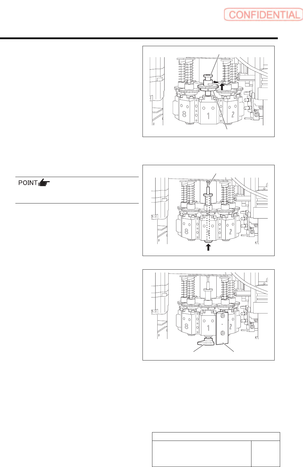
3. Put a pull-out jig on the upper part of
the spline nut and pull the small gear
quietly to move.
4. Change the direction of the small gear
so that position of the set screw on the
left of the small gear is on the front
toward you.
5. Quietly lower the small gear from the
pull-out jig and move it to the spline
nut.
11 Adjust the phase.
1. Insert the inner shaft temporarily.
Pay attention to phases of the inner shaft and
the spline nut.
2. Turn the inner shaft so that the
marking (scribing line) on the inner
shaft is directed to the front.
3. Install a phase adjusting jig (1) with
cap screws (2-CP3x14).
4. Install the phase adjusting jig (2) at
the lower side of the inner shaft.
Pull-out jig
Small gear
Inner shaft
Phase adjusting jig (2)
Phase adjusting jig (1)
Adjustment
HLGB-10414-01
Phase Adjustment for Nozzle
SHEET
6/7
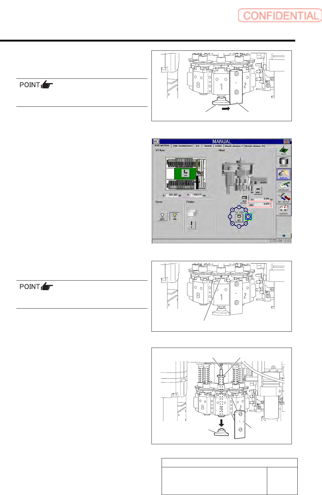
5. Turn the inner shaft and the phase
adjusting jig (2) to lightly press them
against the phase adjusting jig (1).
Now check that the marking on the inner shaft
is directed toward you.
6. Check that current position of the RN
axis is 0° on the axis operation screen.
7. Tighten the sect screw (left) for the
small gear to 15[cN・m].
Check that the small gear is as high as the large
gear.
8. Remove the phase adjusting jig (1) and
phase adjusting jig (2) from the head.
9. Remove the inner shaft and the
pull-out jig from the head.
Phase adjusting jig (2)
Phase adjusting jig (1)
Set screw (Left)
Phase adjusting
jig (2)
Phase adjusting
jig (1)
Pull-out jig Inner shaft
Adjustment
HLGB-10414-01
Phase Adjustment for Nozzle
SHEET
7/7
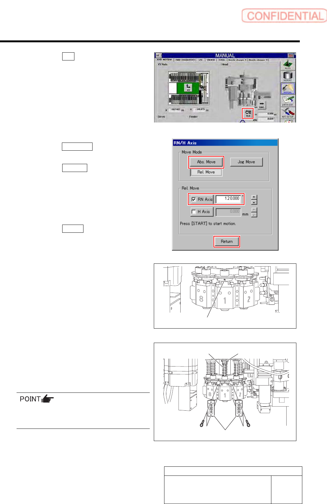
10. Click the R.H button on the AXIS
MOTION screen.
11. Click the Abs. Move button on the
RN/H-axis screen.
12. Click the RN-Axis button and input
“120” into the input space.
13. Press the [START] button on the
operation panel.
The RN axis absolute-moves to a position of
120°.
14. Click the Return button to close the
RN/H axis screen.
15. Tighten the sect screw (right) for the
small gear to 15[cN・m].
12 Install the spring and the spring holder to the
inner shaft.
13 Tighten the cap screws (2-CP3x10) to
40[cN・m] and install the mechanical valve.
Tighten 2-CP3x10 for fixing mechanical valve on
the upper and lower sides alternately little by
little.
14 Turn on the VACUUM breaker.
Set screw (Right)
Spring holder
Spring
Mechanical valve