MAN00000772_SI-G200BB_SVCPDFA.pdf - 第342页
Adjustment HLGB-10417-01 Adjustment of Cassette Float Sensor Height SHEET 2/3 5. Check that there’ s no gap between the cassette table and suppor t column mounting face. Thickness gauge of t=0.02should n ot be inserted b…
Adjustment
HLGB-10417-01
Adjustment of Cassette Float Sensor
Height
SHEET
1/3
Adjustment of Cassette Float Sensor Height
This section describes a procedure to adjust the height of the cassette float sensor by using feed
adjusting jig and cassette float sensor height adjusting jig.
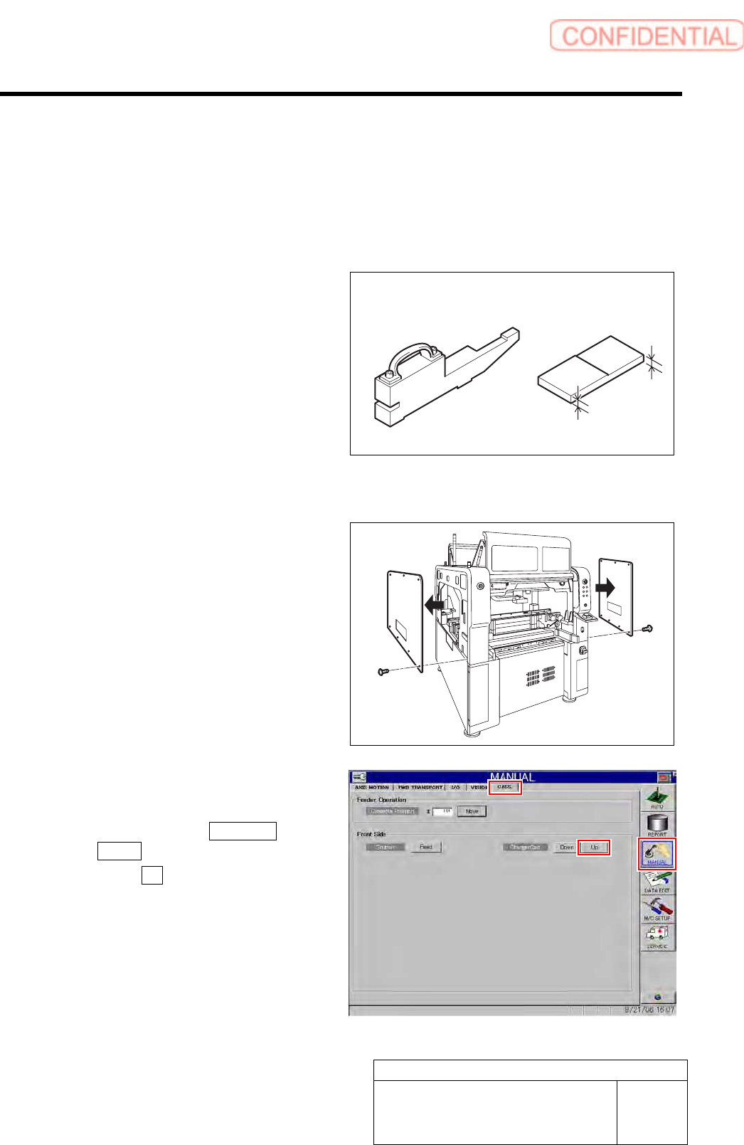
[Necessary jigs]
• Feed adjusting Jig
• Cassette float sensor height adjusting Jig
[Procedure]
1 Remove the upper side panels on both sides
of the unit.
2 Set the replacing carrier.
1. Set the replacing carrier on the unit.
2. Click in an order of MANUAL menu
CASS. tab.
3. Click the Up button for the replacing
carrier on the front or rear side.
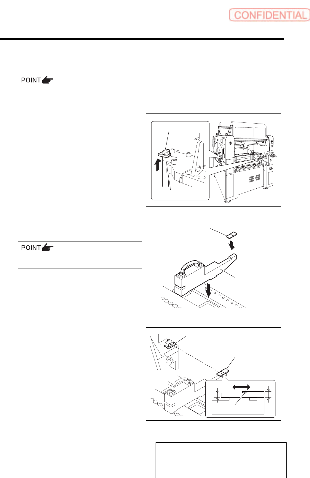
4. Press the [START] button on the
operation panel.
The cassette table on the replacing carrier is
locked.
Feed adjusting jig
Cassette float sensor
height adjusting jig
6 mm
5 mm
Adjustment
HLGB-10417-01
Adjustment of Cassette Float Sensor
Height
SHEET
2/3
5. Check that there’s no gap between the
cassette table and support column
mounting face.
Thickness gauge of t=0.02should not be
inserted between the mounting faces.
3 Pull the bracket for the cassette float sensor
up to the upper end and temporarily tighten.
1. Loosen the cap screws (2-M4) on the
attachment bracket for the cassette
float sensors (left side: BS-63R, right
side: BS-63T) installed in the vertical
frame of the base stand.
2. Pull the bracket up to the upper end
and temporarily fasten.
4 Check that sensitivity level of BS-63R is
MAX.
5 Set the feed adjusting jig to the No.1
position on the cassette table.
There should be no gap between the feed
adjusting jig and the cassette table.
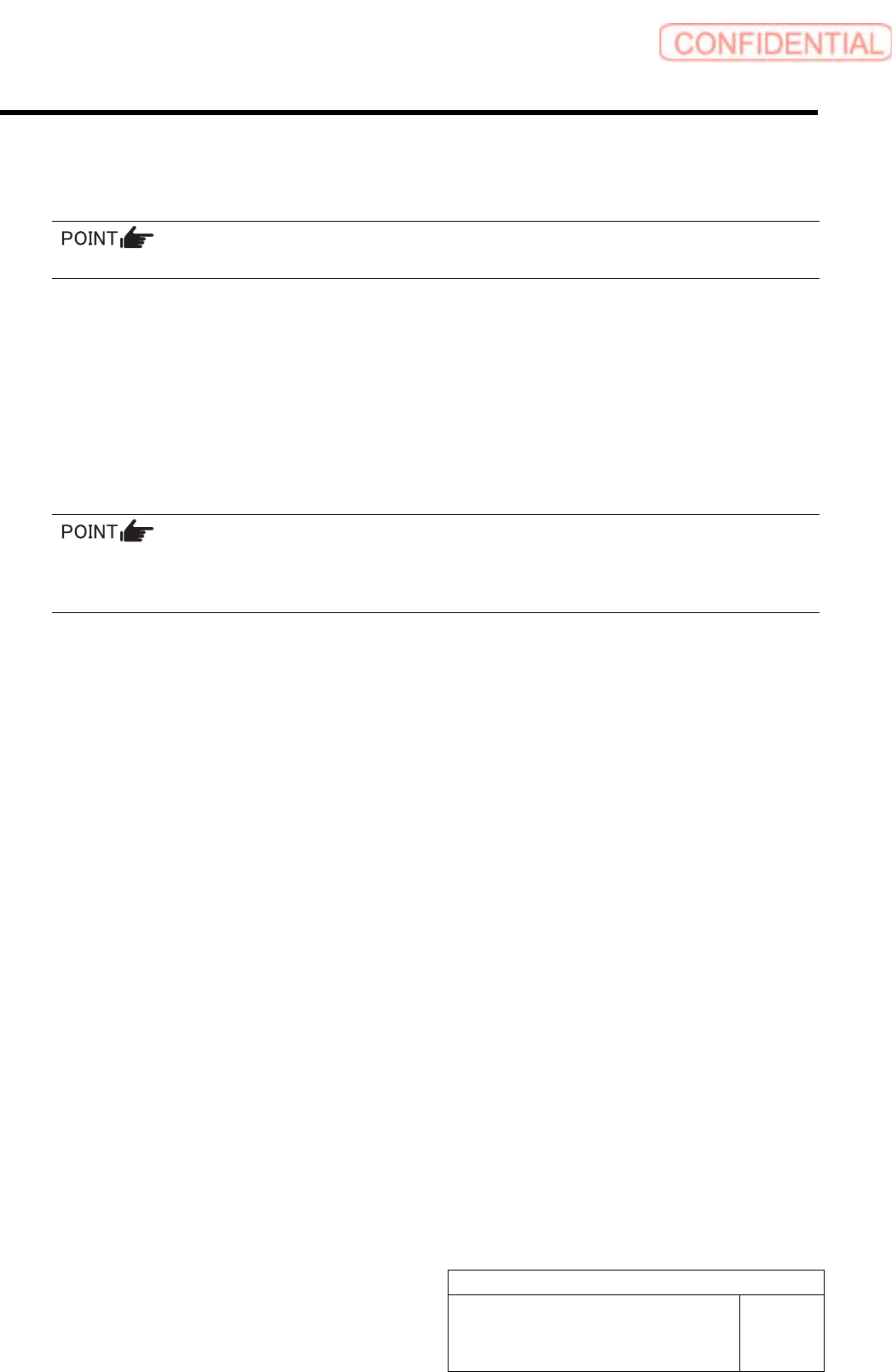
6 Place the cassette float sensor height
adjusting jig on the end of the feed adjusting
jig.
7 Adjust the height of the BS-63R.
1. Adjust the BS-63R attachment bracket
position so that the LED for the
BS-63R lights up at a part of 5 mm on
the cassette float sensor height
adjusting jig, and the LED
extinguishes at a part of 6 mm.
2. Fasten the cap screw to fix the
attachment bracket.
3.
Again, move the cassette float sensor
height adjusting jig back and forth to
check that the LED turns ON/OFF well.
Attachment bracket
Cassette float sensor
Feed adjusting jig
Cassette float sensor
height adjusting jig
Cassette float sensor
height adjusting jig
Attachment bracket
5 mm
6 mm
Optical axis
Adjustment
HLGB-10417-01
Adjustment of Cassette Float Sensor
Height
SHEET
3/3
8 Adjust the height of the BS-63T attachment bracket at the position of No.39 on the cassette table.
1. Set the feed adjusting jig and cassette float sensor height adjusting jig on the position of
No.39 on the cassette table.
There should be no gap between the feed adjusting jig and the cassette table.
2. Adjust the height of the BS-63T attachment bracket in the same procedure as in the
procedure 7.
9 Check that the LED for the BS-63R normally responds at the position of No.20 on the cassette
table.
Check that the LED for the BS-63R lights up at a part of 5 mm on the cassette float sensor height adjusting jig, and the
LED extinguishes at a part of 6 mm.
10 Finally, again, check that the LEDs for the BS-63R and BS-63T normally respond at the positions of
No.1, 20 and 39 on the cassette table.
If the height is respectively adjusted at the positions of No.1, 20 and 39 on the cassette table, response
condition adjusted at the previous position varies. Be sure to check response of the sensor at the 3
locations after adjustment.
11 Remove the jig.
1. Remove the cassette float sensor adjusting jig and feed adjusting jig.
2. Remove the replacing carrier.
12 Also, adjust the cassette float sensors (BS-375T, BS-375R) on the rear side in the same procedure
as the procedures 3 to 11.