MAN00000772_SI-G200BB_SVCPDFA.pdf - 第345页
Adjustment HLGB-10418-01 Adjustment of PWB S topper Sensor SHEET 2/2 4 Adjust sensitivity of the PWB stopper sensor . 1. Make adjustment by turning th e sensitivity adjustment v olume of the sensor amplifier so that the …
Adjustment
HLGB-10418-01
Adjustment of PWB Stopper Sensor
SHEET
1/2
Adjustment of PWB Stopper Sensor
[Procedure]
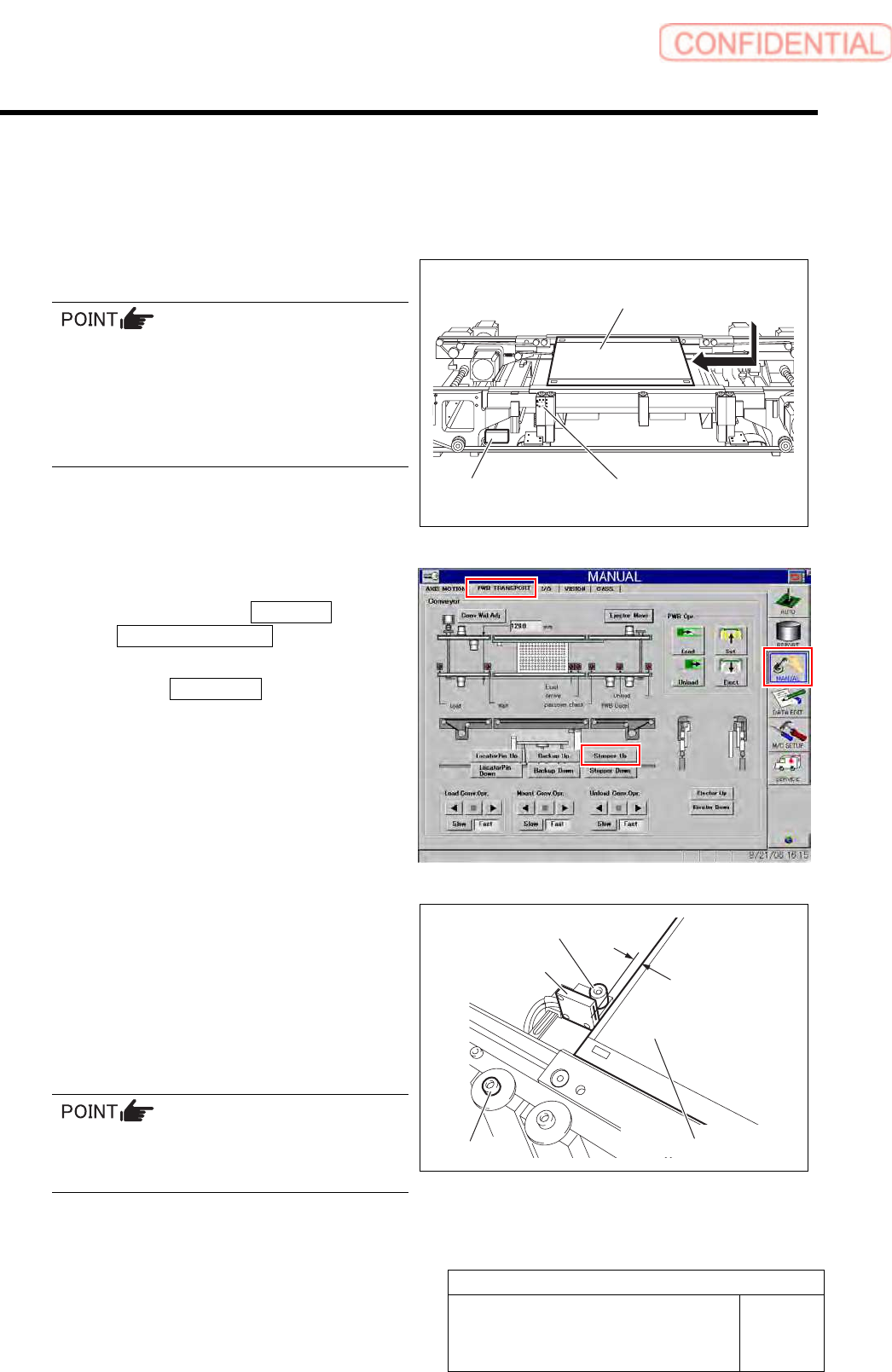
1 Set PWB on the conveyor.
Any PWB sized to be mountable on this
machine can be allowed.
Mountable PWB:
- Minimum PWB dimension: 50 x 50 mm
- Maximum PWB dimension: 460 x 360 mm
- PWB thickness: 0.5 to 2.6 mm
2 Raise the PWB stopper.
1. Click in an order of MANUAL menu
PWB TRANSPORT tab to open the
PWB TRANSPORT screen.
2. Click the Stopper Up button to raise
the PWB stopper.
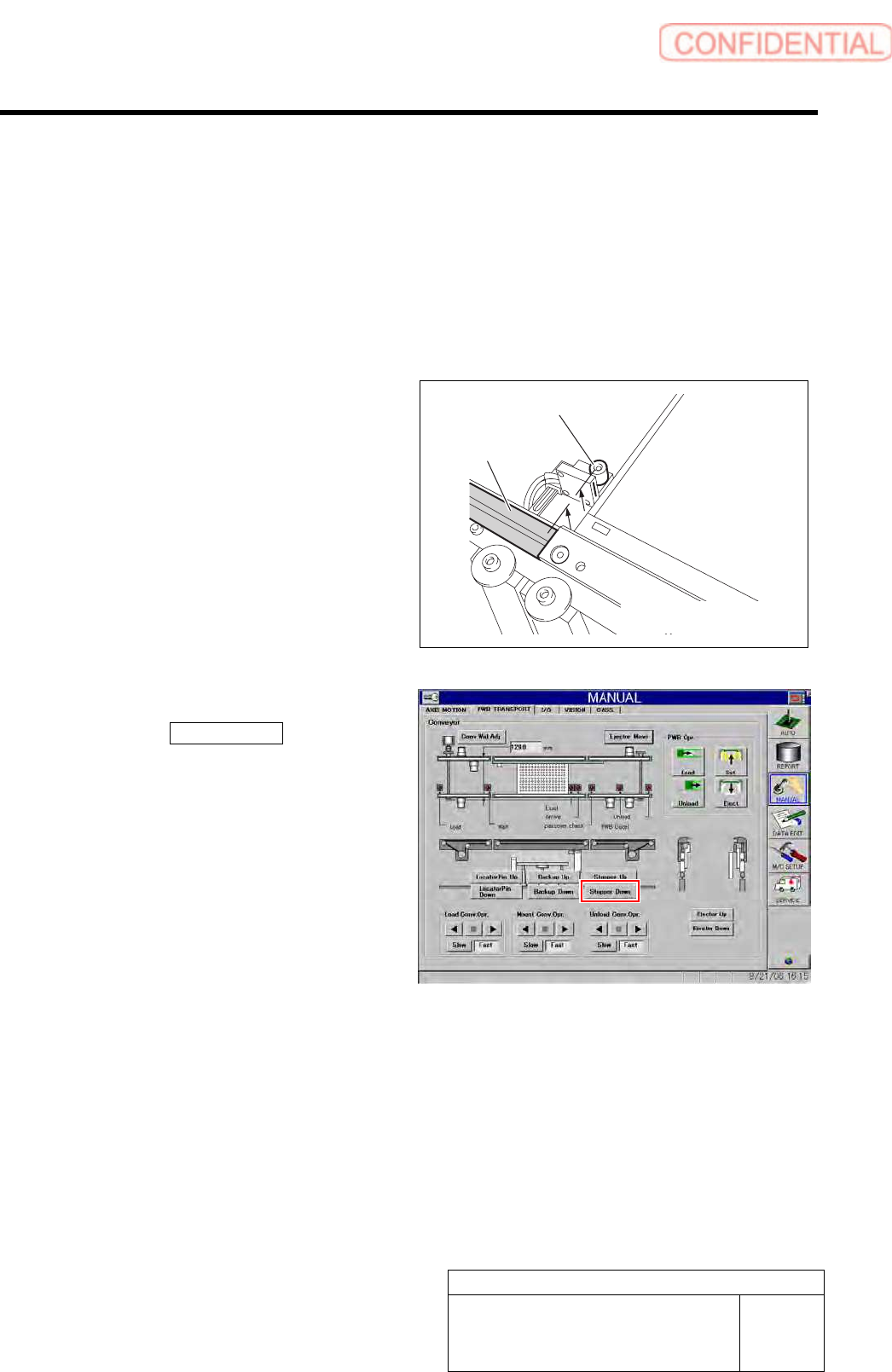
3 Adjust gap between PWB end face and
PWB stopper sensor to 2mm.
1. Loosen the fixing screws for PWB
stopper sensor.
2. Adjust the position of the sensor so
that the gap between the PWB and the
PWB stopper sensor.
The gap can be easily adjusted by inserting a
hexagon wrench of 2 mm between the PWB and
the PWB stopper.
3. Tighten the fixing screws for the PWB
stopper sensor.
PWB stopper sensor
2 mm
PWB
PWB stopper
PWB
PWB stopper sensor
Sensor amplifier
Fixing screw
Adjustment
HLGB-10418-01
Adjustment of PWB Stopper Sensor
SHEET
2/2
4 Adjust sensitivity of the PWB stopper
sensor.
1. Make adjustment by turning the
sensitivity adjustment volume of the
sensor amplifier so that the PWB
stopper sensor is turned on (both of the
green LED and orange LED light up)
at this position.
5 Check that the up end of the PWB stopper is
as high as the conveyor rail.
6 Remove the PWB.
1. Click the Stopper Down button to
lower the reference pin.
2. Remove the PWB on the conveyor.
Conveyor rail
PWB stopper
Adjustment
HLGB-10419-01
Fixed Camera Pickup Check Sensor
Adjustment
SHEET
1/7
Fixed Camera Pickup Check Sensor Adjustment
Perform this operation for fixed camera pickup check sensors on both of front and rear sides.
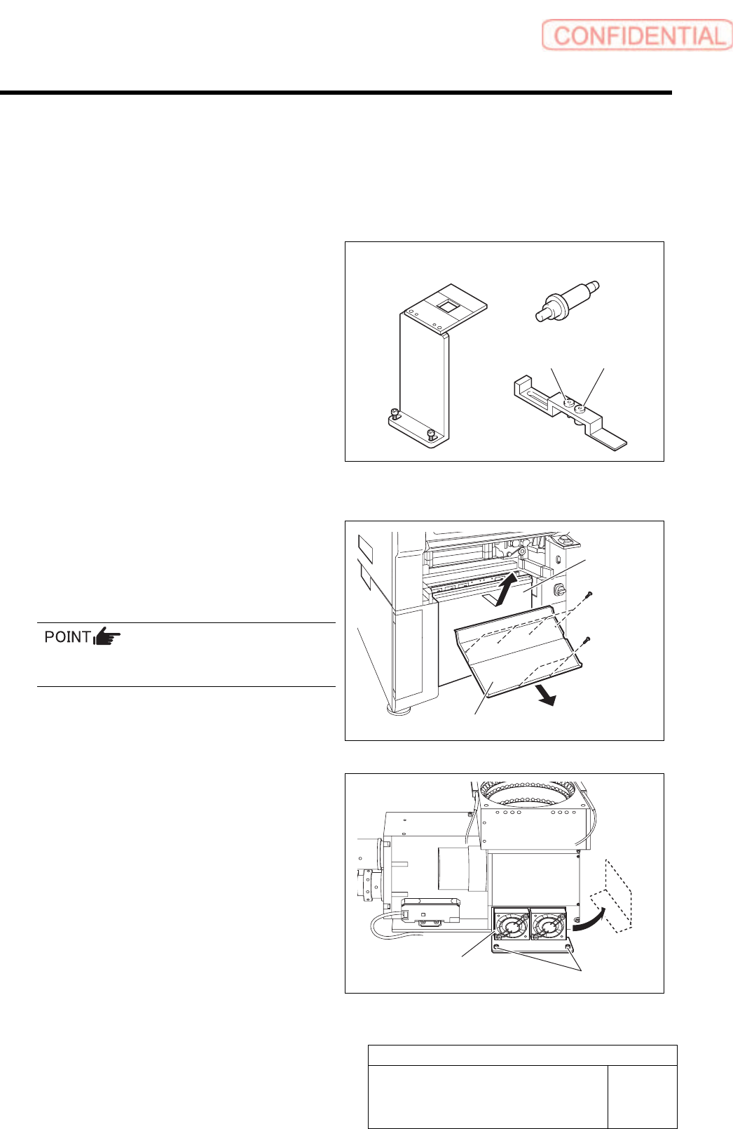
[Necessary jigs]
A Fixed camera Jig base (G200)
B Nozzle Jig for fixed camera
C Fixed camera parts presence/absence
sensor adjustment Jig
D Sensor adjusting nozzle (1)/long thin
E Sensor adjusting nozzle (2)/short thick
[Procedure]
1 Remove the lower cover and shooter on the
front and rear of the unit.
1. Loosen screw (2-+T4x8) to remove the
lower cover.
Tile the lower cover slightly toward you and pull
the fan cable to remove the lower panel.
2. Loosen screw (2-+T4x8) to remove the
shooter.
2 Loosen cap screws (2-CP5x10) fixing the
fixed camera cooling fan to remove the fan.
Temporarily place the removed fan on the side of the
fixed camera.
B
A
C
D E
Lower cover
Shooter
Cap screw
Cooling fan