MAN00000772_SI-G200BB_SVCPDFA.pdf - 第352页
Adjustment HLGB-10419-01 Fixed Camera Pickup Ch eck Sensor Adj ust ment SHEET 7/7 15 Chec k that LED on the sensor amplifier is OFF when light is shielded and ON when light is received. Status of the sensor can be checke…
Adjustment
HLGB-10419-01
Fixed Camera Pickup Check Sensor
Adjustment
SHEET
6/7
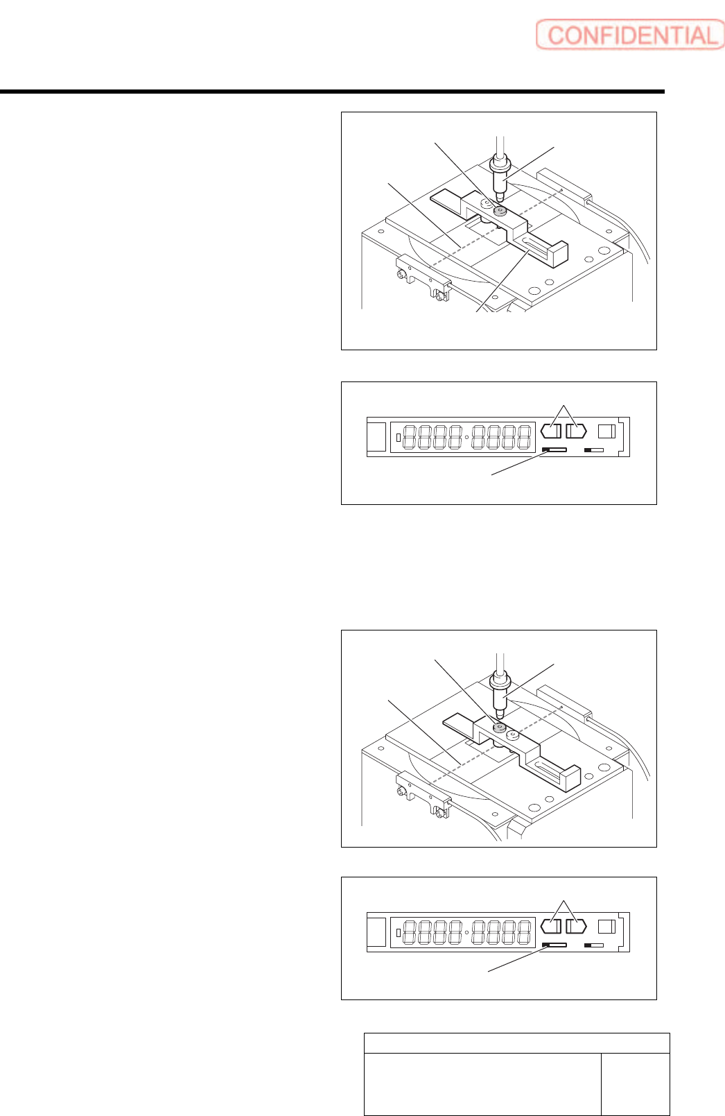
12 Move the sensor adjusting nozzle (1) to right
under the jig nozzle for fixed camera.
13 Put the sensor adjusting nozzle (1) at a
position where optical axis of the sensor is
shielded.
14 Set threshold of the sensor.
1. Turn the SET/RUN selector switch to
SET side.
2. Check that the sensor adjusting nozzle
(1) is just below the fixed camera jig
nozzle.
3. Press either one of DOWN or UP
button.
Light receiving quantity when shielded is
displayed, and then it returns to the indication
before operation.
SET RUN
L D
4. Move the sensor adjusting nozzle (2)
just down to the fixed camera jig
nozzle.
5. Press either one of DOWN or UP
button.
Light receiving quantity when shielded is
displayed, and then it returns to the indication
before operation.
6. Turn the SET/RUN selector switch to
RUN side.
SET RUN
L D
Sensor adjusting
nozzle (1)
Nozzle Jig for
fixed camera
SET/RUN select or switch
Fixed camera parts presence/absence
sensor adjustment Jig
UP/DOWN button
Optical axis
Sensor adjusting
nozzle (2)
Nozzle Jig for
fixed camera
Optical axis
SET/RUN selector switch
UP/DOWN button
Adjustment
HLGB-10419-01
Fixed Camera Pickup Check Sensor
Adjustment
SHEET
7/7
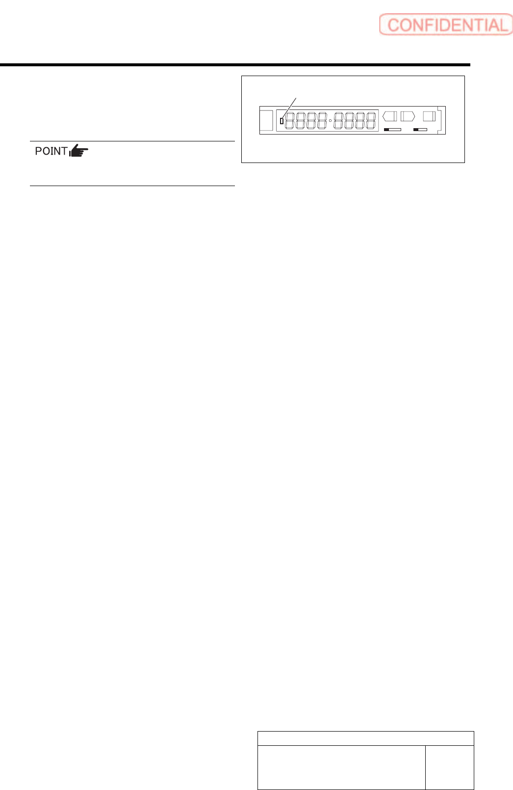
15 Check that LED on the sensor amplifier is
OFF when light is shielded and ON when
light is received.
Status of the sensor can be checked even by the
I/O monitor.
SET RUN
L D
16 This is the end of adjustment for the pickup check sensor.
1. Remove all jigs.
2. Install the cooling fan for fixed camera to the previous position.
3. Install the shooter and the lower cover.
ON/OFF display LED
Adjustment
HLGB-10420-01
Area Sensor Optical Axis Adjustment
SHEET
1/3
Area Sensor Optical Axis Adjustment
Supply section of cassette specification is different from that of tray specification in optical axis
position of area sensor. Be careful of sensor mounting position and hole position for jig before
carrying out optical axis adjustment.
[Necessary jigs]
• Optical axis adjustment jig
[Procedure]
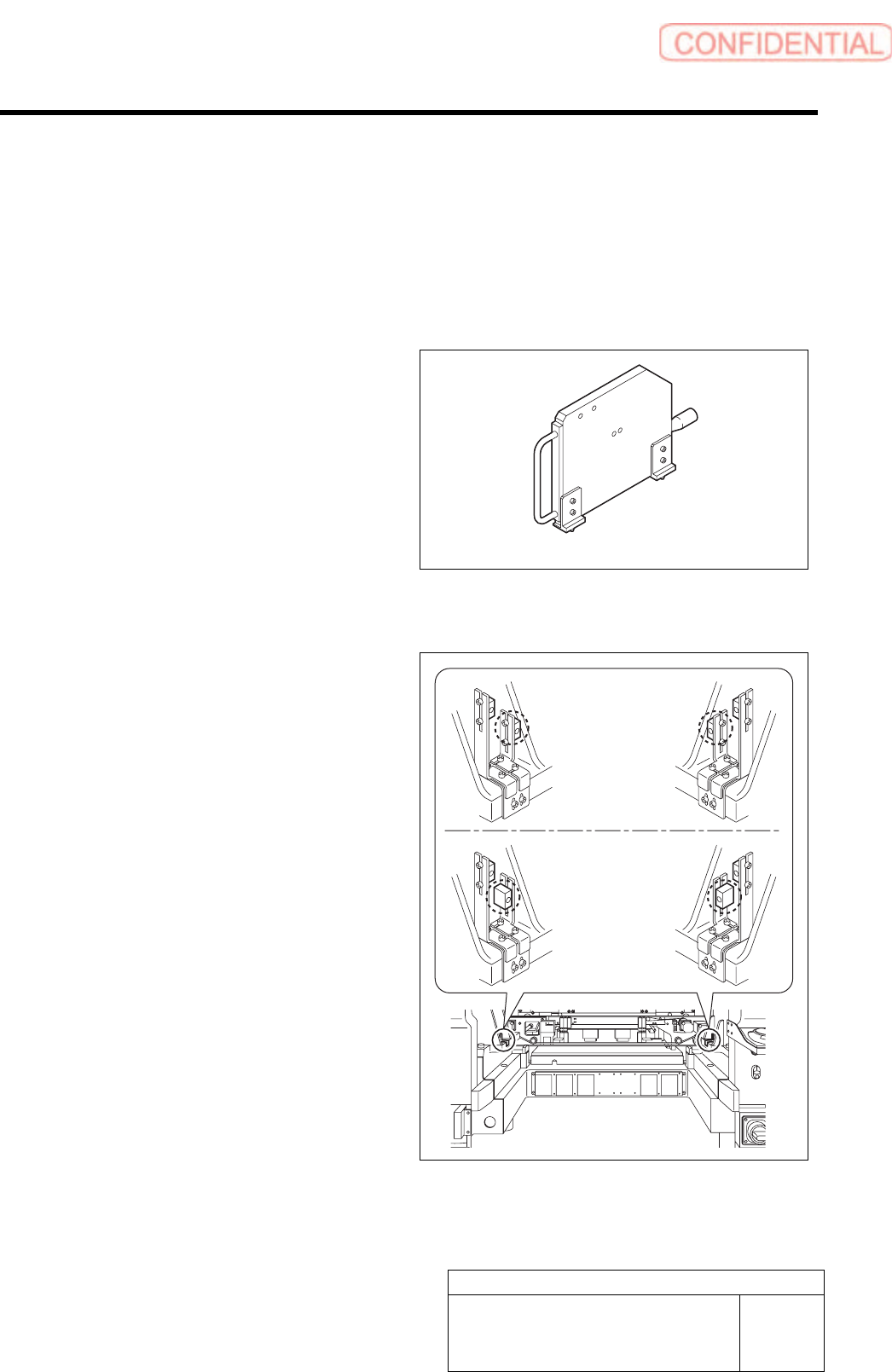
1 Check area sensor mounting position.
Cassette specification is different from tray
specification in area sensor mounting method.
Check that the area sensor is mounted so as to be
suitable for the specification.
Optical axis adjustment jig
Cassette
specification
Tray specification