MAN00000772_SI-G200BB_SVCPDFA.pdf - 第353页
Adjustment HLGB-10420-01 Area Sensor Optical Ax is Adjustment SHEET 1/3 Area Sensor Optical Axis Adjustment Supply section of cassette speci fication is differen t from that of tray specification in o ptical axis positio…
Adjustment
HLGB-10419-01
Fixed Camera Pickup Check Sensor
Adjustment
SHEET
7/7
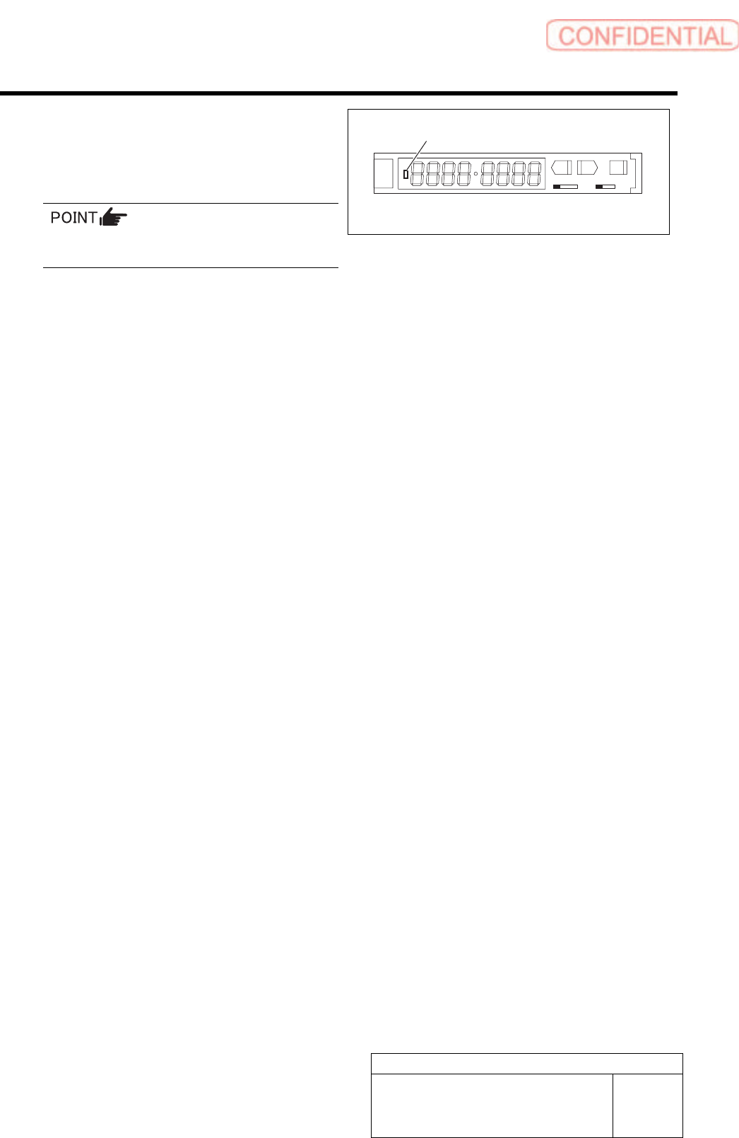
15 Check that LED on the sensor amplifier is
OFF when light is shielded and ON when
light is received.
Status of the sensor can be checked even by the
I/O monitor.
SET RUN
L D
16 This is the end of adjustment for the pickup check sensor.
1. Remove all jigs.
2. Install the cooling fan for fixed camera to the previous position.
3. Install the shooter and the lower cover.
ON/OFF display LED
Adjustment
HLGB-10420-01
Area Sensor Optical Axis Adjustment
SHEET
1/3
Area Sensor Optical Axis Adjustment
Supply section of cassette specification is different from that of tray specification in optical axis
position of area sensor. Be careful of sensor mounting position and hole position for jig before
carrying out optical axis adjustment.
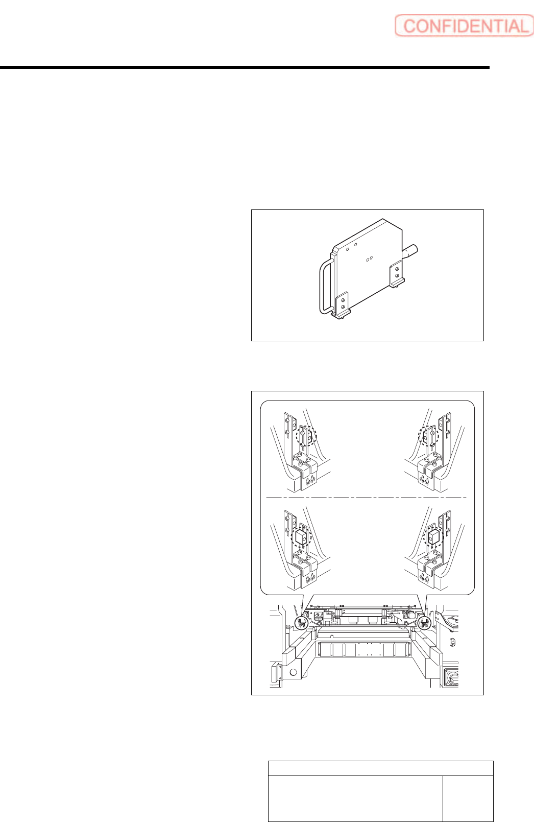
[Necessary jigs]
• Optical axis adjustment jig
[Procedure]
1 Check area sensor mounting position.
Cassette specification is different from tray
specification in area sensor mounting method.
Check that the area sensor is mounted so as to be
suitable for the specification.
Optical axis adjustment jig
Cassette
specification
Tray specification
Adjustment
HLGB-10420-01
Area Sensor Optical Axis Adjustment
SHEET
2/3
2 Turn ON power for the unit to check that the
floodlighting area sensors are installed on
the right side of the unit.
3 Set the optical axis adjustment jig to the
position of supply No. 101.
1. Check that the replacing carrier has
been raised.
2. Set the optical axis adjustment jig on
the cassette table of supply No.101.
There should be no gap between the optical axis
adjustment jig and the cassette table.
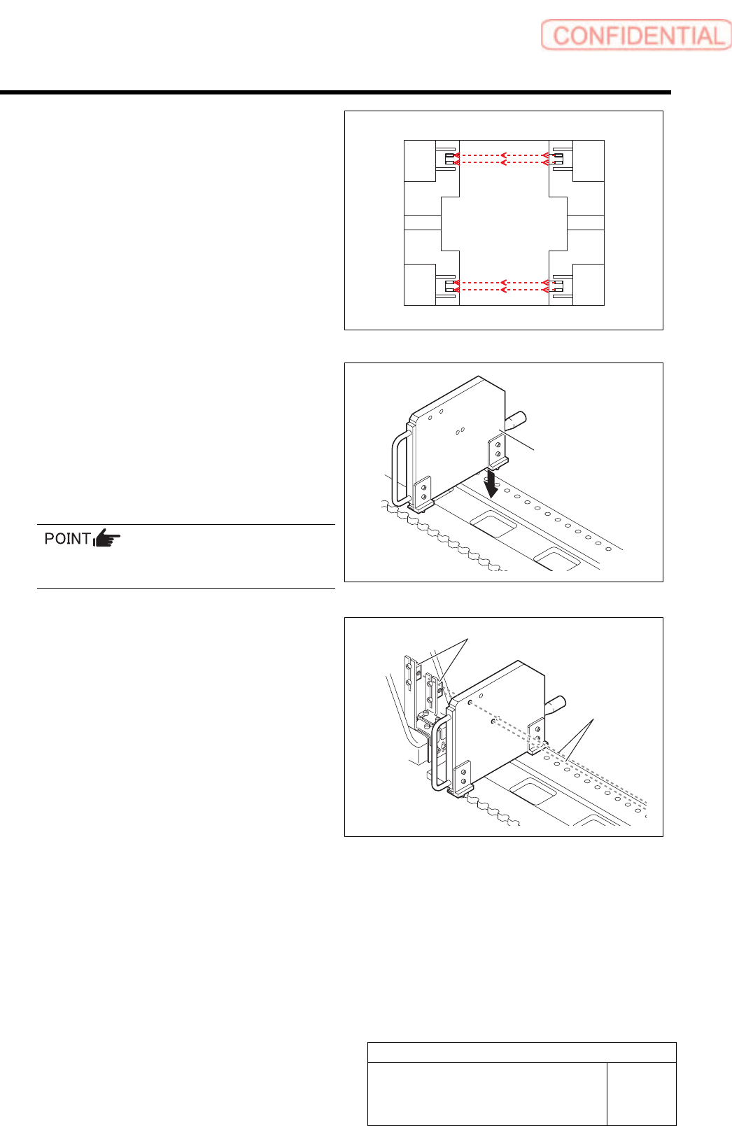
4 Adjust mounting position of the area sensor
so that optical axis of the area sensor
passes through center of the hole on the
optical axis adjustment jig.
The right figure describes how to adjust the area
sensor on the right side as an example. Also adjust
position of the area sensor on the left side in the same
way.
1. Loosen the mounting bolts for the area
sensor to adjust up and downward
positions.
2. Loosen the cap screw on the lower side
of the bracket to adjust forward and
backward position of the area sensor.
Rear
Front
Optical axis
adjustment jig
Area sensor
Optical axis