MAN00000772_SI-G200BB_SVCPDFA.pdf - 第359页
Adjustment HLG B-10 4 22 - 02 Blow F low rate Set up SHEET 2/ 4 2 T urn on the V ACUUM breaker . 1. Loosen scr e ws (2 - +T 4 × 8) to remove t he lo wer c over on t he back of the unit. 2. T u rn on th e V AC UUM br ea k…
Adjustment
HLGB-10422-02
Blow Flow rate Setup
SHEET
1/4
Blow Flow rate Setup
This section describes a procedure to set up blow flow rate. Perform this working on both heads on
the front side and rear side.
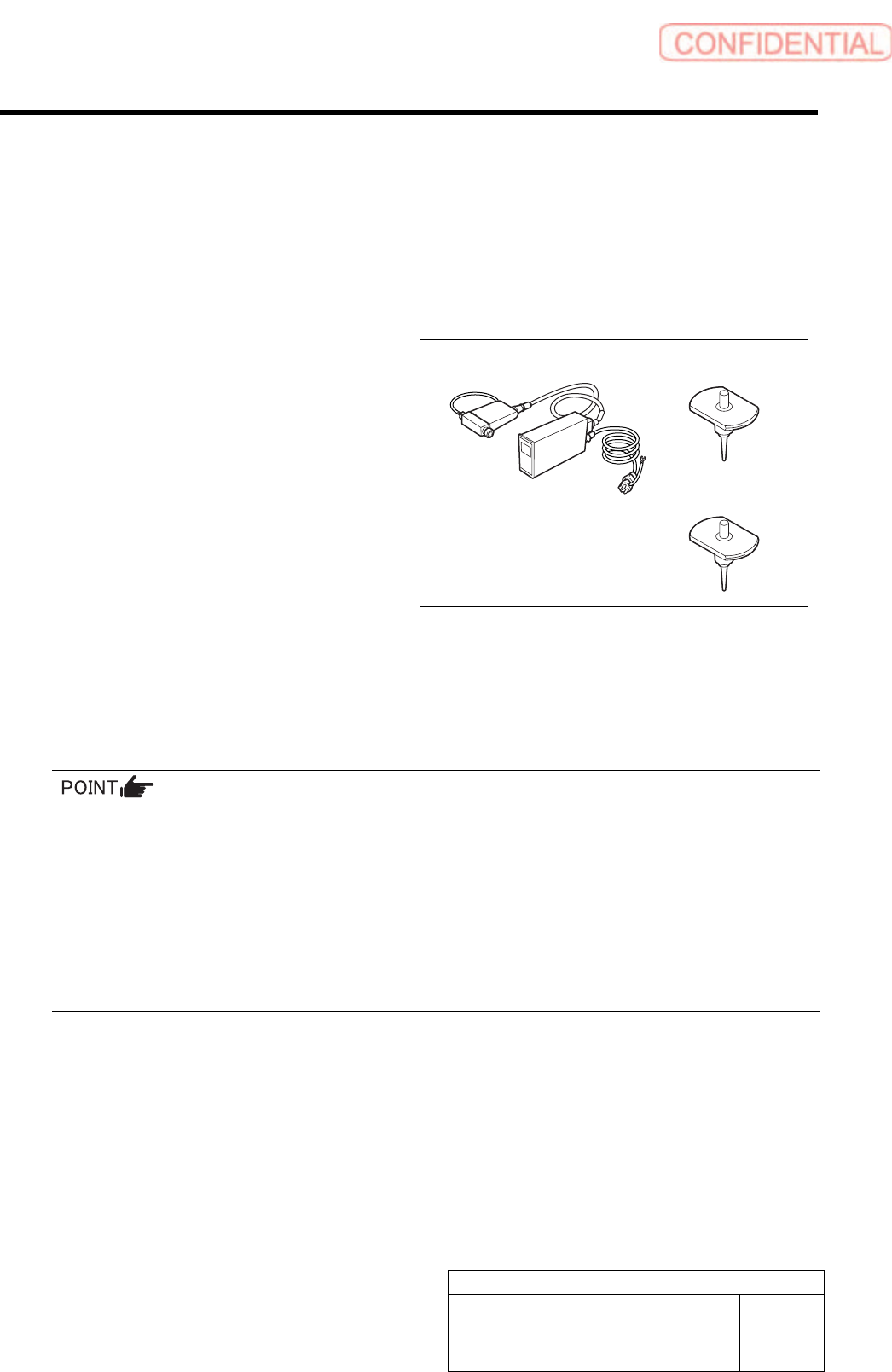
[Necessary jigs]
• Flowmeter
• Flow rate measuring nozzle Jig
(BF1305R)
• Nozzle jig (BF14100): 7 pieces
[Procedure]
1 Prepare flowmeter.
1. Turn on power for the flowmeter and warm up for one minute.
2. Check that the displayed value on the flowmeter is “0±0.009”.
When the displayed value on the flowmeter is not “0±0.009”, adjust the zero point in the following
procedure.
1) Close the IN-OUT part on the flowmeter with tape to warm up for 30 minutes.
2) Carefully remove the serial number seal on the upper of the flowmeter main body until the volume is
seen.
3) Slowly turn the zero adjustment volume (remote from the signal connector) with precision screw driver
to adjust zero point.
4) After zero point adjustment, return the serial number seal to the previous state, and remove the tape
closing the IN-OUT part.
Flowmeter
Flow rate measuring
nozzle Jig
Nozzle jig
Adjustment
HLGB-10422-02
Blow Flow rate Setup SHEET
2/4
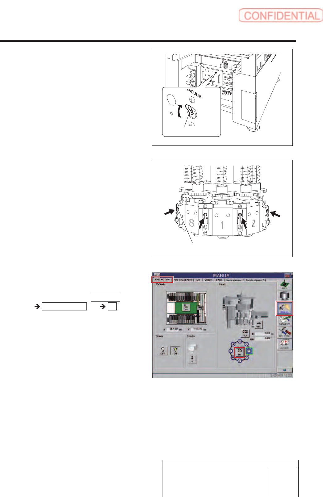
2 Turn on the VACUUM breaker.
1. Loosen screws (2-+T4×8) to remove
the lower cover on the back of the unit.
2. Turn on the VACUUM breaker on the
power unit part.
3 Push the upper part of the levers of the 8
mechanical valves on the head part to be
ready for blow-out.
4 Install the nozzle jigs (BF14100) to the
turrets No.2 to 8.
1. Click in an order of MANUAL menu
AXIS MOTION tab RT button.
Turret RT Axis screen is displayed.
VACUUM breaker
Upper part of lever
Adjustment
HLGB-10422-02
Blow Flow rate Setup
SHEET
3/4
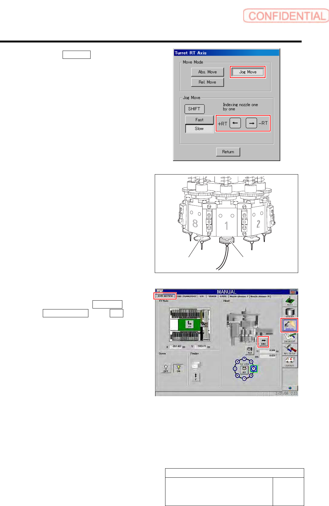
2. Click the Jog Move button in the move
mode.
3. Press the left and right cursor key to
rotate the turrets (No.2 to 8) to fit the
nozzle jig sequentially toward the
front, and install the nozzle jig.
5 Install the flow rate measuring nozzle jig to
the turret No.1.
6 Turn on the blow.
1. Click in an order of MANUAL menu
AXIS MOTION tab VAC button .
VAC SW Pusher screen is displayed.
Flow rate measuring
nozzle jig
Nozzle jig
(AF12080)