MAN00000772_SI-G200BB_SVCPDFA.pdf - 第362页
Adjustment HLGB-10423-01 V acuum Pump Se nsor Setup SHEET 1/2 V acuum Pump Sensor Setup This section describes s etting procedure f or the V acuum Pump sensor located on th e on the inter face panel on the back of the un…
Adjustment
HLGB-10422-02
Blow Flow rate Setup
SHEET
4/4
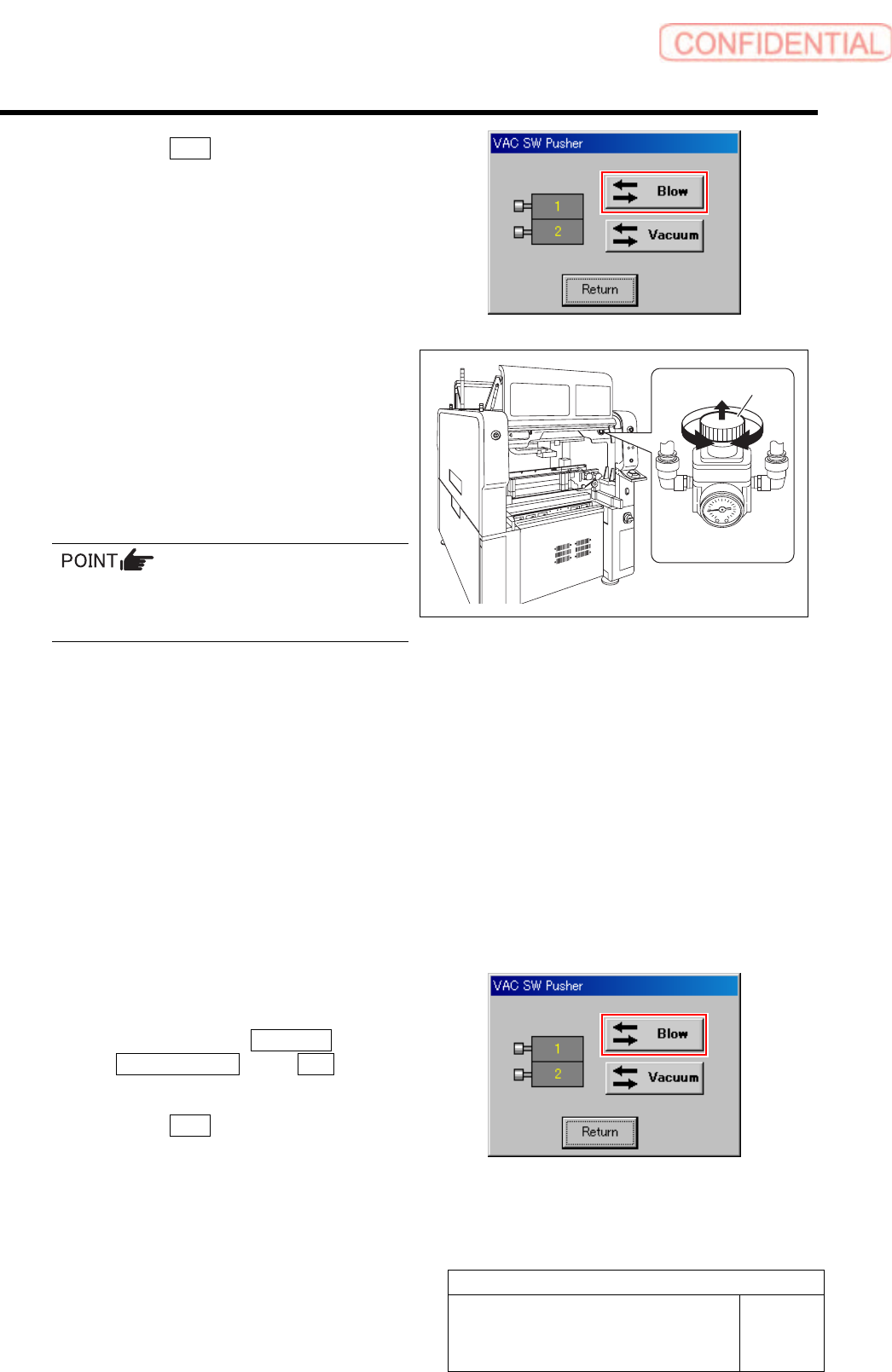
2. Click the Blow button.
The blow is turned on.
3. Check that the value of the blow
regulator is “0.015 to 0.035 MPa” when
in a state of blow.
7 Turn the knob of the blow regulator to set the
measured value of the flowmeter to “0.30
L/min”.
1. Pull out the knob of the blow regulator
upward.
2. Turn the knob to adjust the air
pressure to “0.30 L/min”.
When adjusting the flow rate, make
measurement with the air tube being
straightened wherever possible.
3. Push in the knob downward and lock
the knob.
8 Check the blow flow rate of the turret No.2.
1. Remove the nozzle jig (AF12080) on the turret No.2.
2. Change the flow rate measuring nozzle jig on the turret No.1 onto the turret No.2.
3. Install the nozzle jig (AF12080) to the turret No.1.
4. Check that the measured value of the flowmeter is “0.20 L/min” or more.
5. Check that the value of the blow regulator is “0.015 to 0.035 MPa”.
9 Also check the blow flow rate of the turrets No.3 to 8 in the same procedure as in the procedure 8.
10 After adjusting blow flow rate, return the
blow back to OFF state.
1. Click in an order of MANUAL menu
AXIS MOTION tab VAC button .
VAC SW Pusher screen is displayed.
2. Click the Blow button.
The blow is turned off.
11 Remove the flow rate measuring nozzle jig and nozzle jigs (7 pieces) mounted on the turrets.
Knob
BLOW regulator
Adjustment
HLGB-10423-01
Vacuum Pump Sensor Setup
SHEET
1/2
Vacuum Pump Sensor Setup
This section describes setting procedure for the Vacuum Pump sensor located on the on the interface
panel on the back of the unit.
[Procedure]
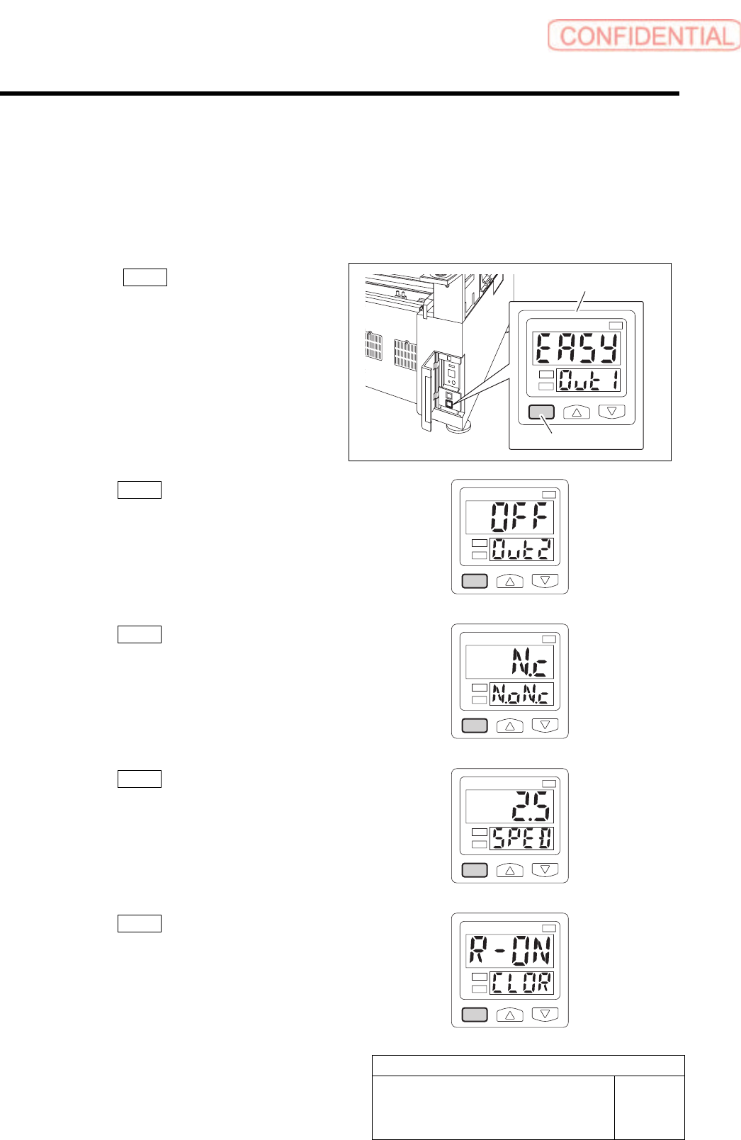
1 Press the MODE button for longer than 2
seconds.
EASY on the display screen.
1
kPa
2
2 Press the MODE button one time.
OFF on the display screen.
1
kPa
2
3 Press the MODE button one time.
N.c on the display screen.
1
kPa
2
4 Press the MODE button one time.
2.5 on the display screen.
1
kPa
2
5 Press the MODE button one time.
R-ON on the display screen.
1
kPa
2
Vacuum Pump sensor
MODE button
Adjustment
HLGB-10423-01
Vacuum Pump Sensor Setup
SHEET
2/2
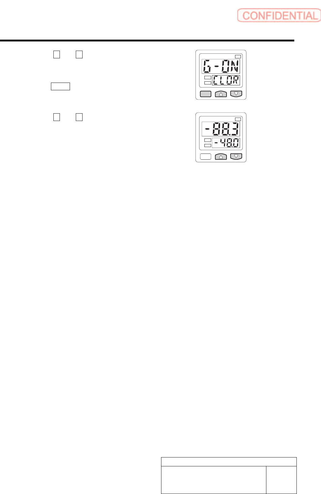
6 Press the U and V button to display the
G-ON.
7 Press the MODE button one time.
1
kPa
2
8 Press the U and V button to display the
-48.0.
Setting is completed.
1
kPa
2