MAN00000772_SI-G200BB_SVCPDFA.pdf - 第47页
Install Tray Unit (Including machine modification) SHEET 8/73 WKGB-10104-03 Installing Tray Unit (Including machine modification) [Y axis OT sensor position change and adjustment (rear head only)] 1 T urn on pow er for t…
Install Tray Unit (Including machine modification)
SHEET
7/73
WKGB-10104-03
Installing Tray Unit
(Including machine modification)
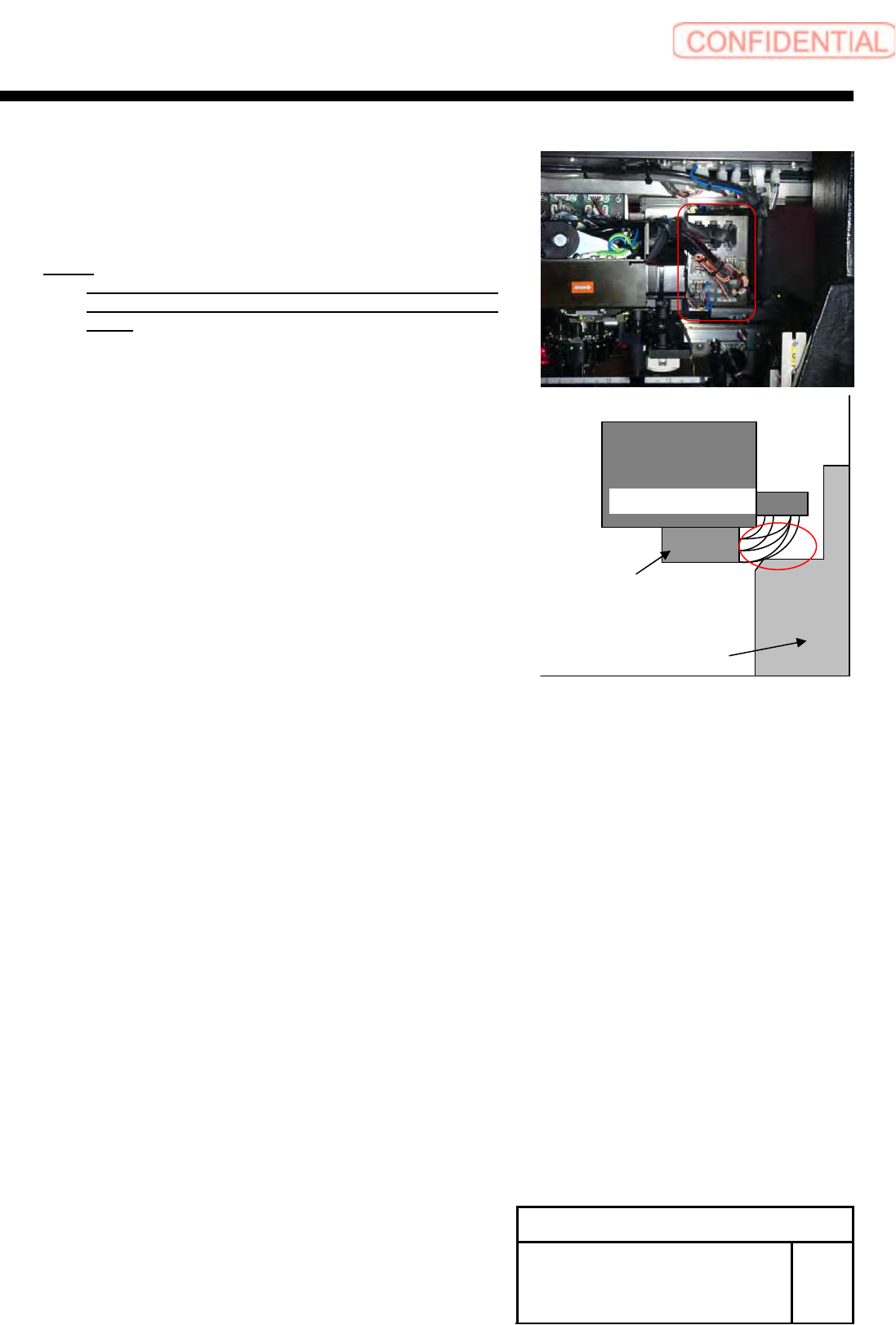
3 Confirm the cable doesn't touch to the pillar
of the frame, when head moved to
mechanical end position(-X direction and +Y
direction).
NOTE:
If the cable touch to pillar of frame, please change
the shape of cable wiring around the connector
panel.
Pillar of frame
Rear Head unit
Rear F-axis unit
This side is Rear side of mounter
Install Tray Unit (Including machine modification)
SHEET
8/73
WKGB-10104-03
Installing Tray Unit
(Including machine modification)
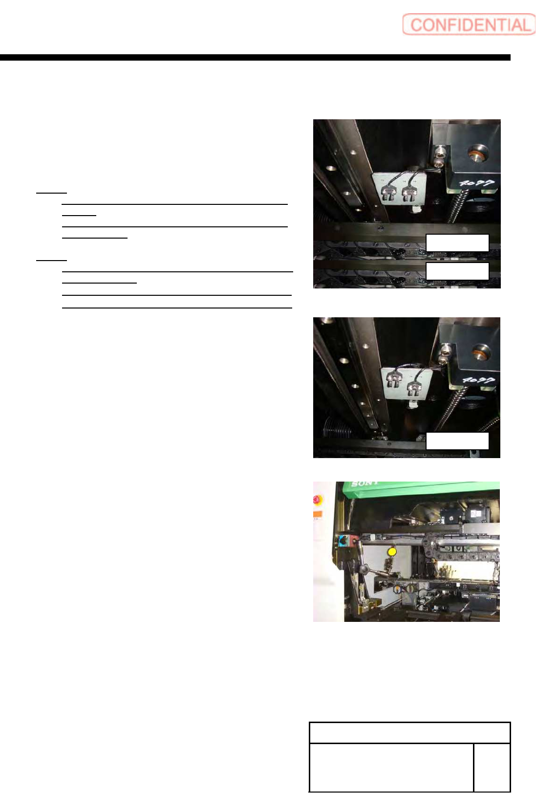
[Y axis OT sensor position change and adjustment (rear head only)]
1 Turn on power for the unit.
2 Change installing positions of 2-CP3x8 and
YR-CCW sensor.
NOTE:
Do not move the sensor brackets and YR-ORG
sensor.
Temporarily fix them because their positions are
adjusted later.
NOTE:
Conditions of positions for mechanical end and
YR-CCW sensor
・When they are within 0.8mm, YR-CCW lights up
・When they are within 1.0mm, YR-CCW lights off
3 Adjust positional relation between the
mechanical end and YR-CCW sensor.
1. Fix magnet stand and pick tester to the frame.
2. Set a dial gauge to zero with the XR frame being at
the mechanical end.
3. Move the XR frame by 0.8mm from the
mechanical end to inside of the unit.
4. Move the YR-CCW sensor and fix it at a position
where the LED on the YR-CCW sensor changes to
lighting up from lighting off.
5. Move the XR frame by 1.0mm from the mechanical
end to inside of the frame, and check that LED on
the YR-CCW sensor lights off.
6. Again move the XR frame by 0.8mm from the
mechanical end to inside of the unit, and check that
LED on the YR-CCW sensor lights up.
After change
Before change
Before change
Install Tray Unit (Including machine modification)
SHEET
9/73
WKGB-10104-03
Installing Tray Unit
(Including machine modification)
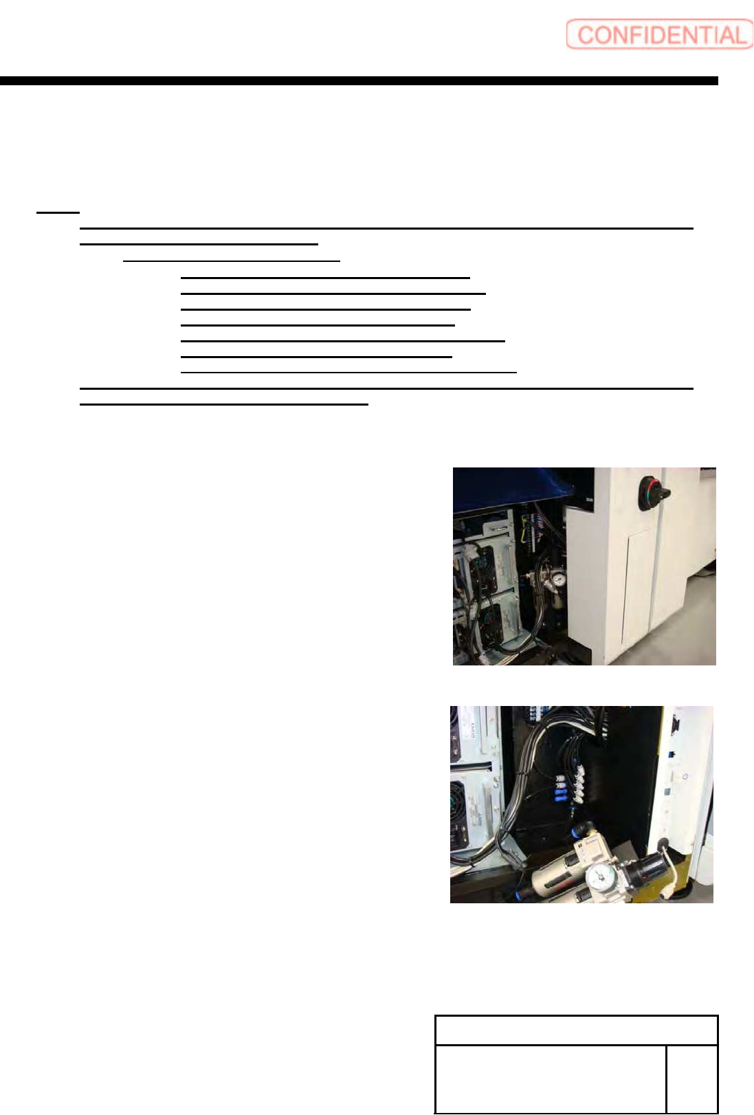
[Additional installation of piping, wiring and installation of tray I/F plate]
1 Additionally install air line for tray unit.
NOTE:
Please arrange the following goods additionally, if you execute the modification to SI-G200
that is older than the 866th machine.
・A-1540-885-A TRAY ASSY KIT
1-834-058-11 CABLE, TRAY CONNECT 3
1-835-002-11 CABLE (JEPMC-W6002-04-E)
3-870-447-01 CAP (SC750-150), SILICON
4-708-465-01 CAP, TUBE (KQ2C06-00)
4-716-434-11 TIE, INSULOCK (AB100 BLACK)
4-761-324-31 REJUICER (KQ2R06-08)
7-632-385-50 TUBE, POLYURETHAN (TU0604B)
Please connect the air-tube that has already been arranged, if you execute the modification to
SI-G200 that is later than the 865th machine.
1. Remove the front center cover and front right cover.
2. Turn OFF the power and shut off air on the primary side.
3. Remove the rear center cover and rear right cover.
4. Loosen the bolts 2-CP4x10 to move position of the air
three-point set.