MAN00000772_SI-G200BB_SVCPDFA.pdf - 第49页
Install Tray Unit (Including machine modification) SHEET 10/73 WKGB-10104-03 Installing Tray Unit (Including machine modification) 5. Additionally install the ai r tube of φ 6 (length 2300m m approximately) from the fron…
Install Tray Unit (Including machine modification)
SHEET
9/73
WKGB-10104-03
Installing Tray Unit
(Including machine modification)
[Additional installation of piping, wiring and installation of tray I/F plate]
1 Additionally install air line for tray unit.
NOTE:
Please arrange the following goods additionally, if you execute the modification to SI-G200
that is older than the 866th machine.
・A-1540-885-A TRAY ASSY KIT
1-834-058-11 CABLE, TRAY CONNECT 3
1-835-002-11 CABLE (JEPMC-W6002-04-E)
3-870-447-01 CAP (SC750-150), SILICON
4-708-465-01 CAP, TUBE (KQ2C06-00)
4-716-434-11 TIE, INSULOCK (AB100 BLACK)
4-761-324-31 REJUICER (KQ2R06-08)
7-632-385-50 TUBE, POLYURETHAN (TU0604B)
Please connect the air-tube that has already been arranged, if you execute the modification to
SI-G200 that is later than the 865th machine.
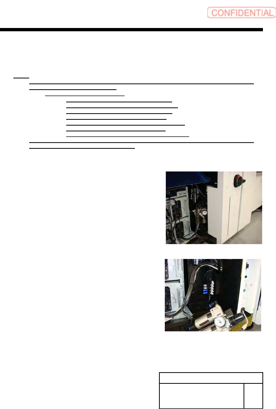
1. Remove the front center cover and front right cover.
2. Turn OFF the power and shut off air on the primary side.
3. Remove the rear center cover and rear right cover.
4. Loosen the bolts 2-CP4x10 to move position of the air
three-point set.
Install Tray Unit (Including machine modification)
SHEET
10/73
WKGB-10104-03
Installing Tray Unit
(Including machine modification)
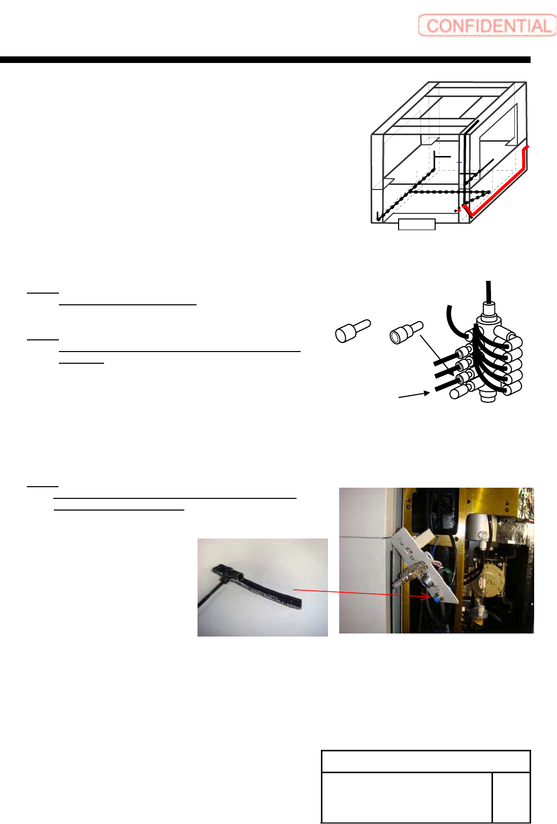
5. Additionally install the air tube ofφ6 (length 2300mm
approximately) from the front of the unit to the rear.
6. Connect the air tube ofφ6 to the manifold.
NOTE:
Use ports closed with plugs.
NOTE:
Change the diameter by reducer to connect to the
manifold.
7. Connect the additionally installed air piping ofφ6 to
the tray I/F on the rear side of the tray.
NOTE:
Block the air port on the obverse side of the tray
I/F panel with bent air tube.
Front
Plug
Reducer
For tray unit
Install Tray Unit (Including machine modification)
SHEET
11/73
WKGB-10104-03
Installing Tray Unit
(Including machine modification)
8. Fix the air three-point set to the previous position.
9. Connect air on the primary side.
10. Install the front right cover with 4-+T4x8 as in the
previous state.
11. Install the front right lower cover with +T4x8.
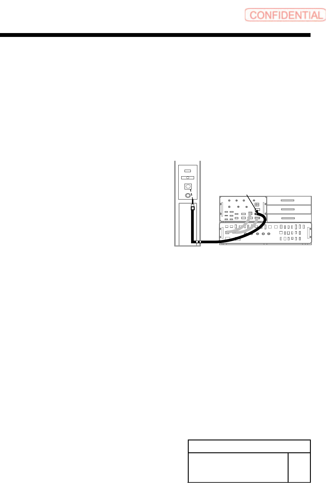
2 Additionally install a tray power cable.
1. Remove the rear center cover and rear right cover.
2. Connect the TY-AC on the tray coupling I/F plate
and PW-3 on the power unit with the tray power
cable.
PW3
TY
-
TY
-
ML
TY
-
C
TY
-
AC
A