MAN00000772_SI-G200BB_SVCPDFA.pdf - 第56页
Install Tray Unit (Including machine modification) SHEET 17/73 WKGB-10104-03 Installing Tray Unit (Including machine modification) 3. Connect the EI0-14 of EX2 I/O cable to the CN14 of EX2 I/O board and wire EX2 I/O ca b…
Install Tray Unit (Including machine modification)
SHEET
16/73
WKGB-10104-03
Installing Tray Unit
(Including machine modification)
5 Install wiring of EX2 I/O cable.
NOTE:
Please arrange the following goods additionally, if you execute the modification to SI-G200
that is older than the 866th machine.
・A-1540-885-A TRAY ASSY KIT
1-834-058-11 CABLE, TRAY CONNECT 3
1-835-002-11 CABLE (JEPMC-W6002-04-E)
3-870-447-01 CAP (SC750-150), SILICON
4-708-465-01 CAP, TUBE (KQ2C06-00)
4-716-434-11 TIE, INSULOCK (AB100 BLACK)
4-761-324-31 REJUICER (KQ2R06-08)
7-632-385-50 TUBE, POLYURETHAN (TU0604B)
Please connect the cable that has already been arranged, if you execute the modification to
SI-G200 that is later than the 865th machine.
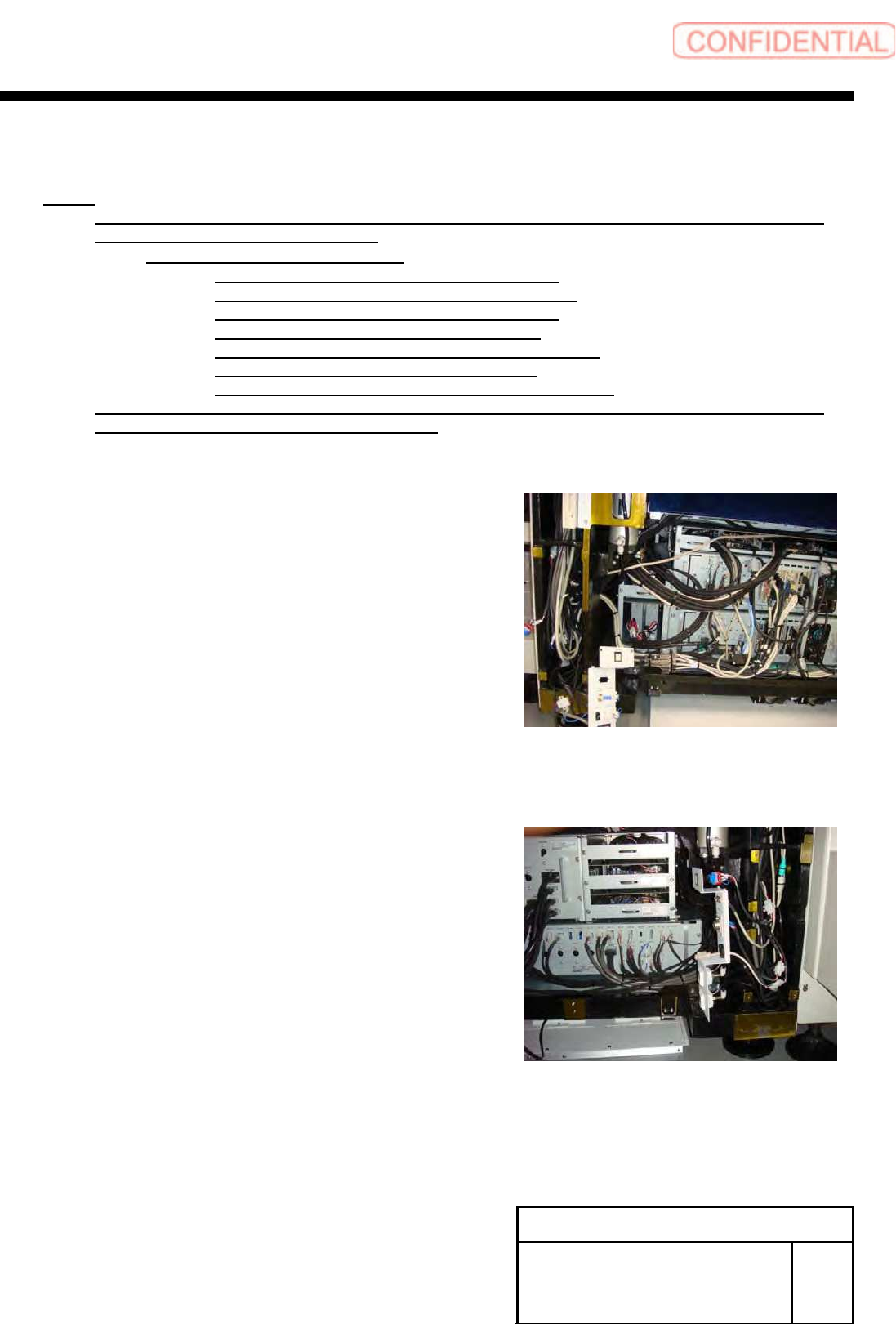
1. Remove the front center cover and left lower front
cover.
2. Remove the rear center cover and left lower rear
cover.
Install Tray Unit (Including machine modification)
SHEET
17/73
WKGB-10104-03
Installing Tray Unit
(Including machine modification)
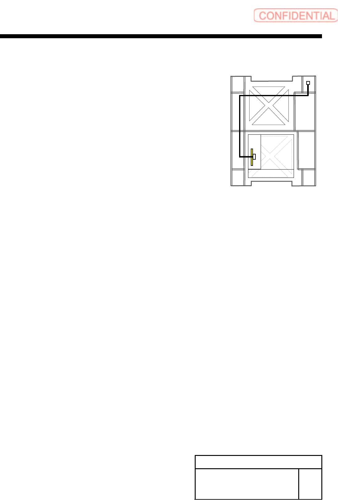
3. Connect the EI0-14 of EX2 I/O cable to the CN14
of EX2 I/O board and wire EX2 I/O cable to rear
side of mounter.
4. Connect the TY-CTL3 of the EX2 I/O cable to
TY0-CTR3 of the tray I/F panel.
Front
Install Tray Unit (Including machine modification)
SHEET
18/73
WKGB-10104-03
Installing Tray Unit
(Including machine modification)
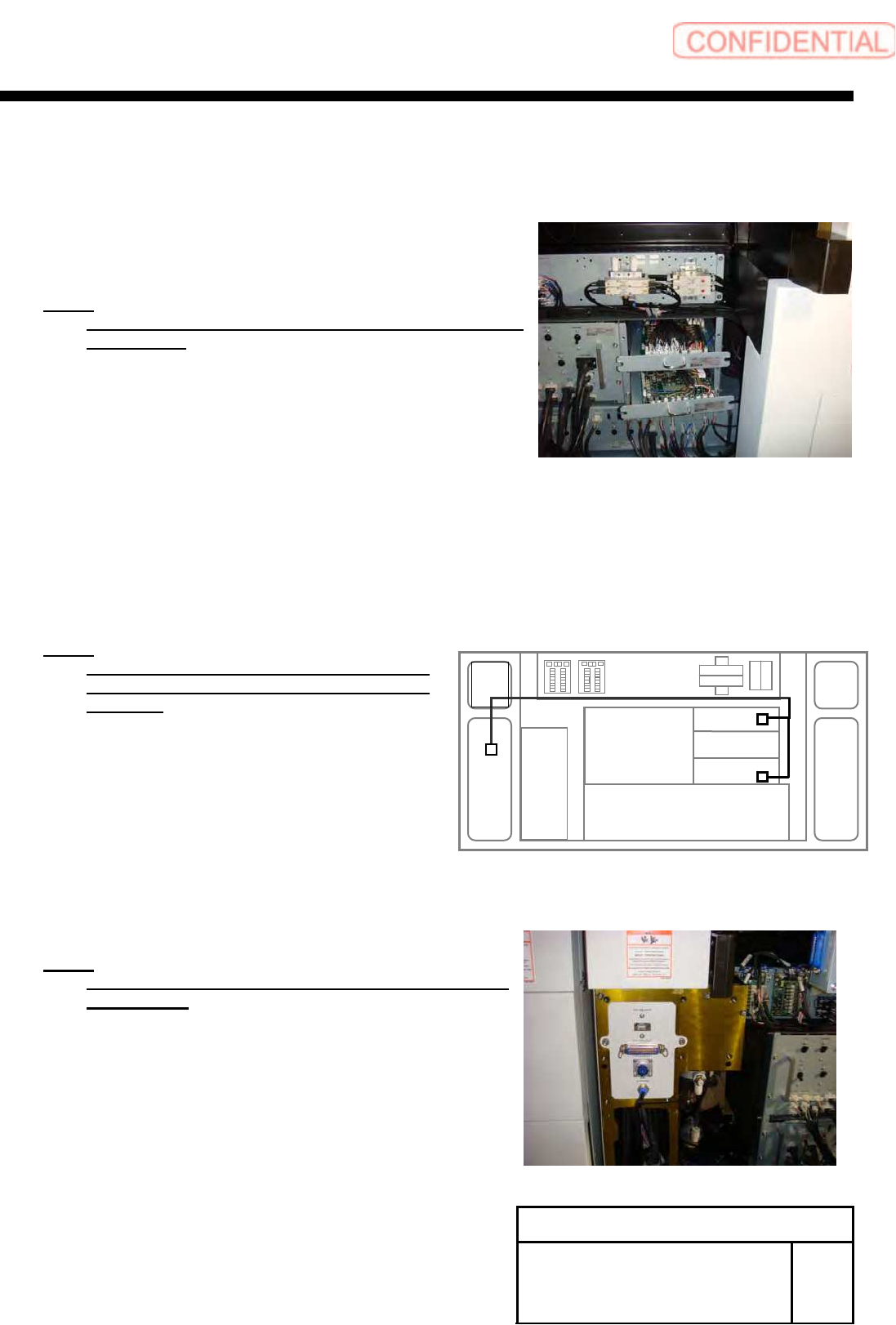
6 Connection of tray coupling cable
1. Loosen the CP6x12 and pull pout the I/O unit 1
and I/O unit 3 to a position where working can be easily
performed.
NOTE:
Do not forcedly pull them out. Otherwise, the cable may
be damaged.
2. Connect the ELR-12 to CN12 on the emergency
I/L Board in the I/O unit 3, and connect SR-5,
SR-16 to CN5, CN16 on the safety relay board in
the I/O unit.
NOTE:
Remove the jumper connector connected
CN12 on E I/L board and connected CN5 on
SR board.
7 Install the tray I/F panel with the
2-CP6X8.
NOTE:
Connect terminal connectors to the TY-MLOUT and
TY-CTLOUT.
I/O 2
I/O 1
I/O 3
TY-CTL1
TY-CTL2