MAN00000772_SI-G200BB_SVCPDFA.pdf - 第60页
Install Tray Unit (Including machine modification) SHEET 21/73 WKGB-10104-03 Installing Tray Unit (Including machine modification) [Change in shape and inst allation of right lower rear cover] 1 Loosen the +T4x8 to remov…
Install Tray Unit (Including machine modification)
SHEET
20/73
WKGB-10104-03
Installing Tray Unit
(Including machine modification)
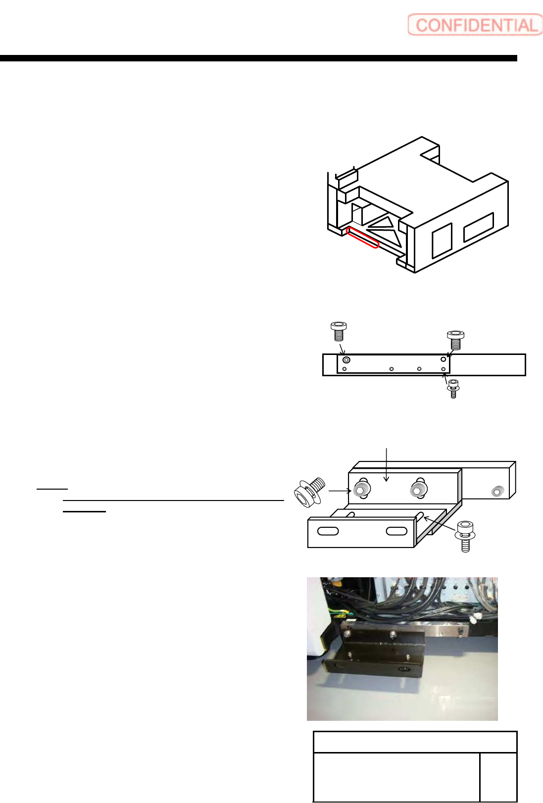
[Installation of joint block, coupling bracket]
1 Install the base block, joint block (1) and
joint block (2) in this sequence to the
rear side of the unit.
1. Fix the base block to the rear side of the frame
using the CP12x20、CP12x35.
2. Fix the joint block(1) and joint block(2) to base
block using the CP12x20, CP12x35.
NOTE:
Temporarily fix the joint block (1) and joint
block (2).
Rear
Base block
CP12x20
CP12x35
CP8x35
W8
Joint block(1)
Joint block (2)
CP12x16
W12
CP6x14
W6
Install Tray Unit (Including machine modification)
SHEET
21/73
WKGB-10104-03
Installing Tray Unit
(Including machine modification)
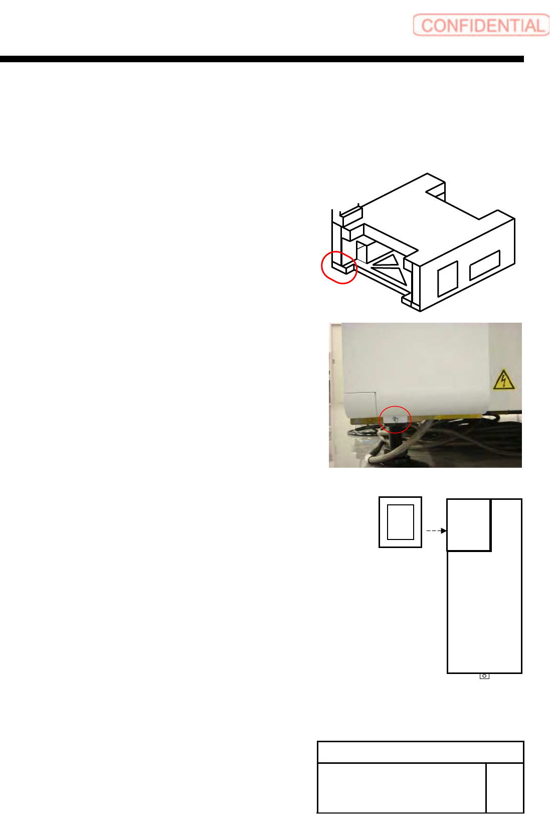
[Change in shape and installation of right lower rear cover]
1 Loosen the +T4x8 to remove the right
lower rear cover.
2 Loosen the 3-CP4x6 to remove the cover
(standard) for joint.
3 Install the cover (tray specification) for
joint with the 3-CP4x6.
Rear
Install Tray Unit (Including machine modification)
SHEET
22/73
WKGB-10104-03
Installing Tray Unit
(Including machine modification)
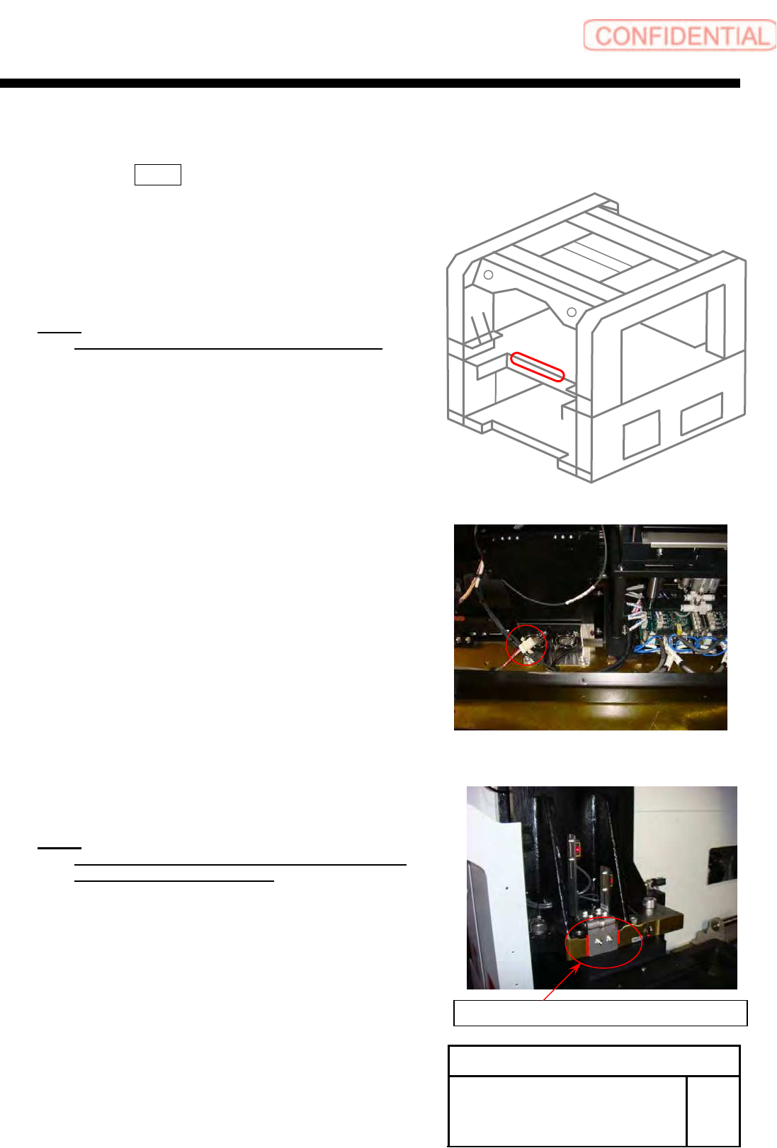
[Installation of cassette table and cassette floating detection sensor]
1 Pull out 375 on the connector wired
on the back of the shoot bracket, and
move it near the center of the shoot
bracket.
NOTE:
After working, bind the wires with INSULOCK.
2 Mark the installing position of the area
sensor bracket.
NOTE:
Mark the installing positions of both of the right
and left area sensor brackets.
Mark end section of the bracket.
REAR