MAN00000772_SI-G200BB_SVCPDFA.pdf - 第600页
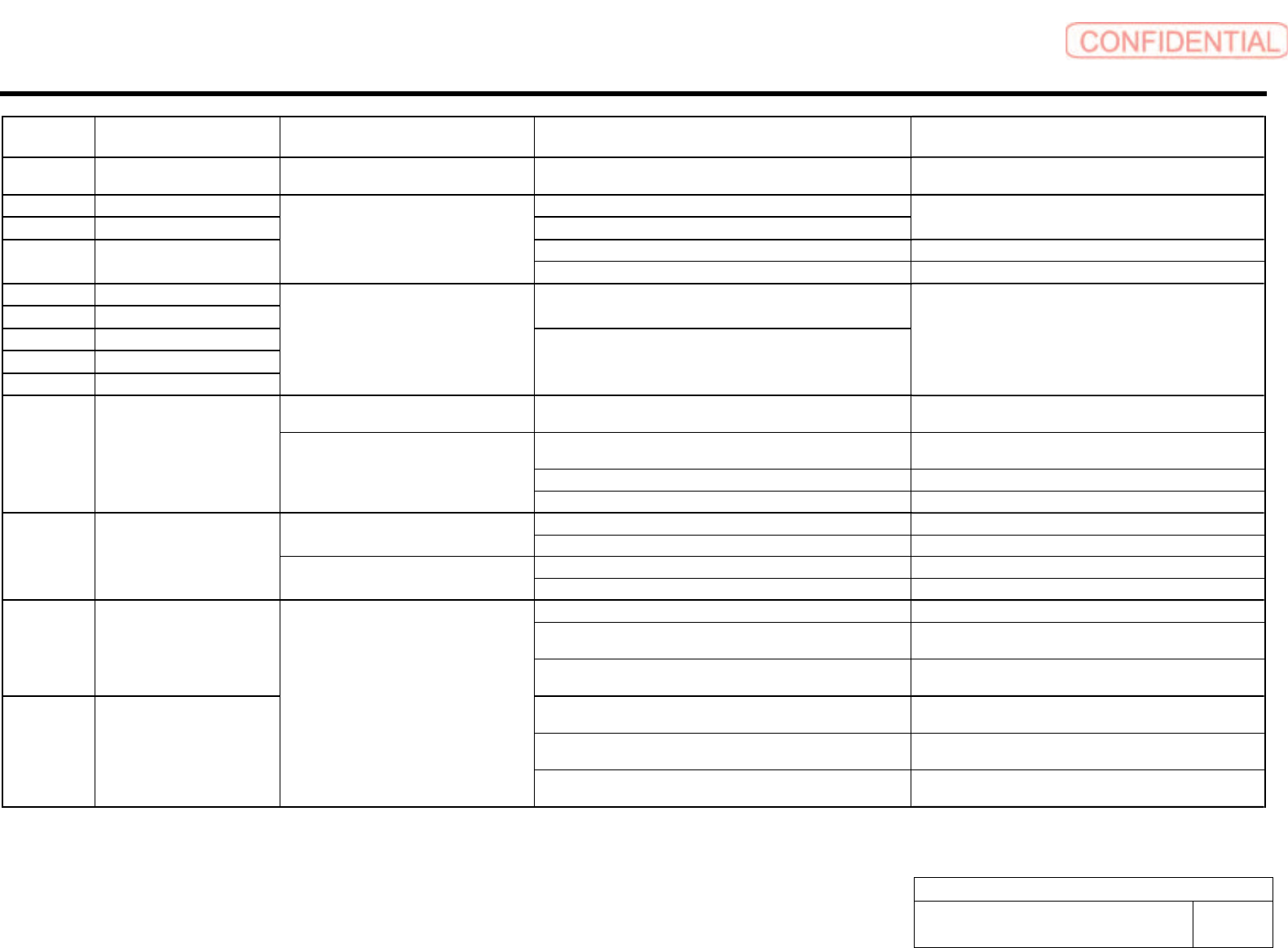
Alarm List for the Servo Pack "S igma-III" Series (SGDS type) BBGB-10101-01 Alarm List for the Servo Pack "Sigma-III" Series (SGDS type) SHEET 1 1/18 Alarm Display Alarm Name Situation at Alarm Occurr…
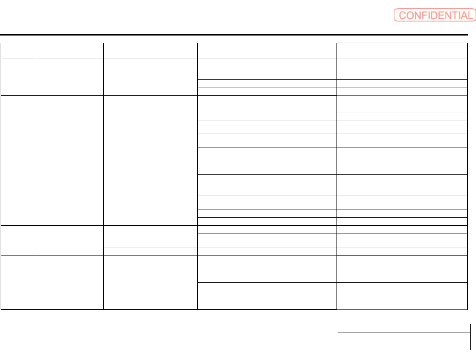
Alarm List for the Servo Pack "Sigma-III" Series (SGDS type)
BBGB-10101-01
Alarm List for the Servo Pack
"Sigma-III" Series (SGDS type)
SHEET
10/18
Alarm
Display
Alarm Name Situation at Alarm Occurrence Cause Corrective Actions
A.8A2 Fully-closed Serial Encoder
Sensor Error (Incremental)
Occurred when the control power supply
was turned ON or during operation.
A linear encoder fault occurred. Replace the linear encoder.
A.b31 Current Detection Error 1 The current detection circuit for the Phase U is faulty.
A.b32 Current Detection Error 2 The current detection circuit for the Phase V is faulty.
Replace the SERVOPACK.
The detection circuit for the power supply is faulty. Replace the SERVOPACK. A.b33 Current Detection Error 3
Occurred when the control power supply
was turned ON or during operation.
The servomotor cable is disconnected. Check the motor wiring.
A.bF0 System Alarm 0
A.bF1 System Alarm 1
A SERVOPACK board fault occurred.
A.bF2 System Alarm 2
A.bF3 System Alarm 3
A.bF4 System Alarm 4
Occurred when the control power supply
was turned ON.
A SERVOPACK board fault occurred.
Replace the SERVOPACK.
Occurred when the control power supply
was turned ON.
A SERVOPACK board fault occurred. Replace the SERVOPACK.
The order of phase-U, -V, and -W in the servomotor wiring is
incorrect.
Correct the servomotor wiring.
An encoder fault occurred. Replace the servomotor.
A.C10 Servo Overrun Detected
Occurred when the servo was ON or a
reference was input.
A SERVOPACK fault occurred. Replace the SERVOPACK.
An encoder fault occurred. Replace the servomotor. Occurred when the control power supply
was turned ON.
A SERVOPACK board fault occurred. Replace the SERVOPACK.
An encoder fault occurred. Replace the servomotor.
A.C80 Absolute Encoder Clear Error
and Multi turn Limit Setting
Error
Occurred when an encoder alarm was
cleared and reset.
A SERVOPACK board fault occurred. Replace the SERVOPACK.
The encoder wiring and the contact are incorrect. Correct the encoder wiring.
Noise interference occurred due to incorrect encoder cable
specifications.
Use tinned annealed copper twisted-pair or twisted-pair
shielded wire with a core of at least 0.12 mm
2
(0.0002 in
2
).
A.C90 Encoder Communications
Error
Noise interference occurred because the wiring distance for the
encoder cable is too long.
The wiring distance must be 20m (65.6 ft) max.
The noise interference occurred on the signal line because the
encoder cable is bent and the sheath is damaged.
Correct the encoder cable layout.
The encoder cable is bundled with a high-current line or near a
high-current line.
Correct the encoder cable layout so that no surge is
applied.
A.C91 Encoder Communications
Position Data Error
Occurred when the control power supply
was turned ON or during operation.
The FG varies because of the influence from machines on the
servomotor side, such as welder.
Make the grounding for the machine separately from PG
side FG.
Alarm List for the Servo Pack "Sigma-III" Series (SGDS type)
BBGB-10101-01
Alarm List for the Servo Pack
"Sigma-III" Series (SGDS type)
SHEET
11/18
Alarm
Display
Alarm Name Situation at Alarm Occurrence Cause Corrective Actions
Noise interference occurred on the signal line from the encoder. Take a measure against noise for the encoder wiring.
Excessive vibration and shocks were applied to the encoder. Reduce the machine vibration or mount the servomotor
securely.
An encoder fault occurred. Replace the servomotor.
A.C92 Encoder Communications
Timer Error
Occurred when the control power supply
was turned ON or during operation.
A SERVOPACK board fault occurred. Replace the SERVOPACK.
An encoder fault occurred. Replace the servomotor. A.CA0 Encoder Parameter Error Occurred when the control power supply
was turned ON.
A SERVOPACK board fault occurred. Replace the SERVOPACK.
The encoder wiring and contact are incorrect. Correct the encoder wiring.
Noise interference occurred due to incorrect encoder cable
specifications.
Use tinned annealed copper twisted-pair or twisted-pair
shielded wire with a core of at least 0.12 mm
2
(0.0002 in
2
).
Noise interference occurred because the wiring distance for the
encoder cable is too long.
The wiring distance must be 20m (65.6 ft) max.
Noise interference occurred on the signal line, because the
encoder cable is bent and the sheath is damaged.
Correct the encoder cable layout.
The encoder cable is bundled with a high-current line or near a
high-current line.
Correct the encoder cable layout so that no surge is
applied.
The FG varies because of the influence from the servomotor
side machines, such as welder.
Ground the machine separately from PG side FG.
Noise interference occurred on the signal line from the encoder. Take measures against noise for the encoder wiring.
Excessive vibration and shocks to the encoder was applied. Reduce the machine vibration or mount the servomotor
securely.
An encoder fault occurred. Replace the servomotor.
A.Cb0 Encoder Echo back Error Occurred when the control power supply
was turned ON or during operation.
A SERVOPACK board fault occurred. Replace the SERVOPACK.
The parameter settings for the SERVOPACK are incorrect. Correct the setting of Pn205 (0 to 65535). Occurred when the control power supply
was turned ON.
The multi turn limit value for the encoder is not set or was
changed.
Execute Fn013 at the occurrence of alarm.
A.CC0 Multi-turn Limit Disagreement
Occurred during operation. A SERVOPACK board fault occurred. Replace the SERVOPACK.
Wiring of cable between serial converter unit and SERVOPACK
is incorrect or faulty contact.
Correct the cable wiring.
The specified cable is not used between serial converter unit
and SERVOPACK.
Use the specified cable.
Cable between serial converter unit and SERVOPACK is too
long.
Use 20-m cable max.
A.CF1 Fully-closed Serial Converter
Unit Communications Error
(Reception Error)
Occurred when the control power supply
was turned ON or during operation.
Sheath of cable between serial converter unit and
SERVOPACK is broken.
Replace the cable.
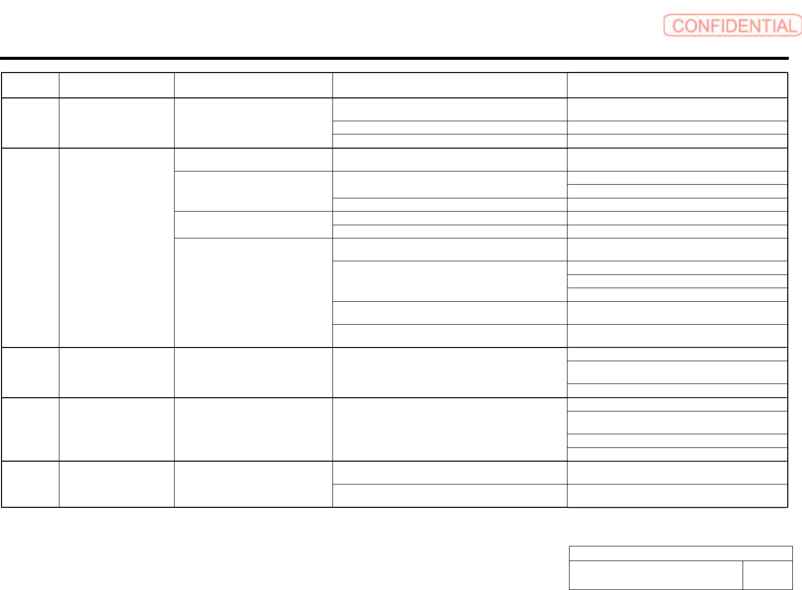
Alarm List for the Servo Pack "Sigma-III" Series (SGDS type)
BBGB-10101-01
Alarm List for the Servo Pack
"Sigma-III" Series (SGDS type)
SHEET
12/18
Alarm
Display
Alarm Name Situation at Alarm Occurrence Cause Corrective Actions
Noise interferes with the cable between serial converter unit
and SERVOPACK.
Correct the wiring around serial converter unit, e.g.,
separating signal line from power line or grounding.
A serial converter unit fault occurred. Replace the serial converter unit.
A.CF2 Fully-closed Serial Converter
Unit Communications Error
(Timer Stopped)
Occurred when the control power supply
was turned ON or during operation.
A SERVOPACK fault occurred. Replace the SERVOPACK.
Occurred when the control power supply
was turned ON.
A SERVOPACK board fault occurred. Replace the SERVOPACK.
Correct the servomotor wiring. The contact in the servomotor U, V, and W wirings is faulty.
Correct the encoder wiring.
Occurred at the servomotor high-speed
operation.
A SERVOPACK board fault occurred. Replace the SERVOPACK.
Wirings of the servomotor U, V, and W are incorrect. Correct the servomotor wiring. The servomotor did not run with position
reference input.
A SERVOPACK board fault occurred. Replace the SERVOPACK.
The SERVOPACK gain adjustment is improper. Increase the speed loop gain (Pn100) and position loop
gain (Pn102).
Adjust slowly the position reference pulse frequency.
Apply the smoothing function.
The position reference pulse frequency is too high.
Correct the electronic gear ratio.
Setting of the parameter Pn520 (Position Error Pulse Overflow
Alarm Level) is incorrect.
Set the parameter Pn520 to proper value.
A.d00 Position Error Pulse Overflow
Normal movement, but occurred with a
long distance reference input.
The servomotor specifications do not meet the load conditions
such as torque and moment of inertia.
Reconsider and correct the load and servomotor capacity.
Do not run the servomotor in servo OFF status.
Make the setting so that the errors are cleared while the
servo is OFF.
A.d01 Position Error Pulse Overflow
Alarm at Servo ON.
Occurred when the control power supply
was turned ON.
• Excessive position errors accumulated while the servo is OFF
• With the setting not to clear the errors while the servo is OFF,
the servomotor was running.
Adjust the detection level.
Do not run the servomotor in servo OFF status.
Make the setting so that the errors are cleared while the
servo is OFF.
Correct the detection level.
A.d02 Position Error Pulse Overflow
Alarm by Speed Limit at Servo
ON.
Occurred when the servomotor was
running.
The servo turned ON with accumulated errors, and reference
pulse was input during operation at the speed limit, therefore,
the errors exceeded the Position Error Pulse Overflow Alarm
Level (Pn520).
Adjust the speed limit level (Pn529) when servo turns ON.
Motor rotation direction and scale installation direction is
opposite.
Install the scale in the opposite direction, or reverse the
setting of fully-closed encoder usage method (Pn002.3).
A.d10 Motor-Load Position Error
Pulse Overflow
Occurred when servo was ON or during
operation.
Position of the load such as stage and scale joint installation are
incorrect.
Check the mechanical joint.