MAN00000772_SI-G200BB_SVCPDFA.pdf - 第602页
Alarm List for the Servo Pack "S igma-III" Series (SGDS type) BBGB-10101-01 Alarm List for the Servo Pack "Sigma-III" Series (SGDS type) SHEET 13/18 Alarm Display Alarm Name Situation at Alarm Occurre…
Alarm List for the Servo Pack "Sigma-III" Series (SGDS type)
BBGB-10101-01
Alarm List for the Servo Pack
"Sigma-III" Series (SGDS type)
SHEET
12/18
Alarm
Display
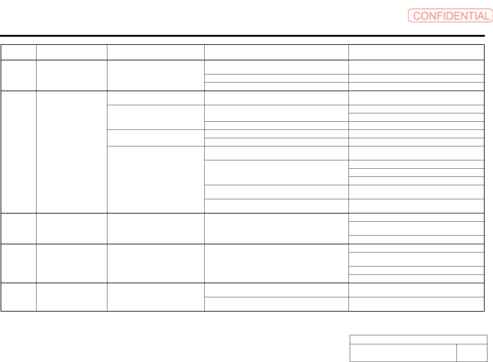
Alarm Name Situation at Alarm Occurrence Cause Corrective Actions
Noise interferes with the cable between serial converter unit
and SERVOPACK.
Correct the wiring around serial converter unit, e.g.,
separating signal line from power line or grounding.
A serial converter unit fault occurred. Replace the serial converter unit.
A.CF2 Fully-closed Serial Converter
Unit Communications Error
(Timer Stopped)
Occurred when the control power supply
was turned ON or during operation.
A SERVOPACK fault occurred. Replace the SERVOPACK.
Occurred when the control power supply
was turned ON.
A SERVOPACK board fault occurred. Replace the SERVOPACK.
Correct the servomotor wiring. The contact in the servomotor U, V, and W wirings is faulty.
Correct the encoder wiring.
Occurred at the servomotor high-speed
operation.
A SERVOPACK board fault occurred. Replace the SERVOPACK.
Wirings of the servomotor U, V, and W are incorrect. Correct the servomotor wiring. The servomotor did not run with position
reference input.
A SERVOPACK board fault occurred. Replace the SERVOPACK.
The SERVOPACK gain adjustment is improper. Increase the speed loop gain (Pn100) and position loop
gain (Pn102).
Adjust slowly the position reference pulse frequency.
Apply the smoothing function.
The position reference pulse frequency is too high.
Correct the electronic gear ratio.
Setting of the parameter Pn520 (Position Error Pulse Overflow
Alarm Level) is incorrect.
Set the parameter Pn520 to proper value.
A.d00 Position Error Pulse Overflow
Normal movement, but occurred with a
long distance reference input.
The servomotor specifications do not meet the load conditions
such as torque and moment of inertia.
Reconsider and correct the load and servomotor capacity.
Do not run the servomotor in servo OFF status.
Make the setting so that the errors are cleared while the
servo is OFF.
A.d01 Position Error Pulse Overflow
Alarm at Servo ON.
Occurred when the control power supply
was turned ON.
• Excessive position errors accumulated while the servo is OFF
• With the setting not to clear the errors while the servo is OFF,
the servomotor was running.
Adjust the detection level.
Do not run the servomotor in servo OFF status.
Make the setting so that the errors are cleared while the
servo is OFF.
Correct the detection level.
A.d02 Position Error Pulse Overflow
Alarm by Speed Limit at Servo
ON.
Occurred when the servomotor was
running.
The servo turned ON with accumulated errors, and reference
pulse was input during operation at the speed limit, therefore,
the errors exceeded the Position Error Pulse Overflow Alarm
Level (Pn520).
Adjust the speed limit level (Pn529) when servo turns ON.
Motor rotation direction and scale installation direction is
opposite.
Install the scale in the opposite direction, or reverse the
setting of fully-closed encoder usage method (Pn002.3).
A.d10 Motor-Load Position Error
Pulse Overflow
Occurred when servo was ON or during
operation.
Position of the load such as stage and scale joint installation are
incorrect.
Check the mechanical joint.
Alarm List for the Servo Pack "Sigma-III" Series (SGDS type)
BBGB-10101-01
Alarm List for the Servo Pack
"Sigma-III" Series (SGDS type)
SHEET
13/18
Alarm
Display
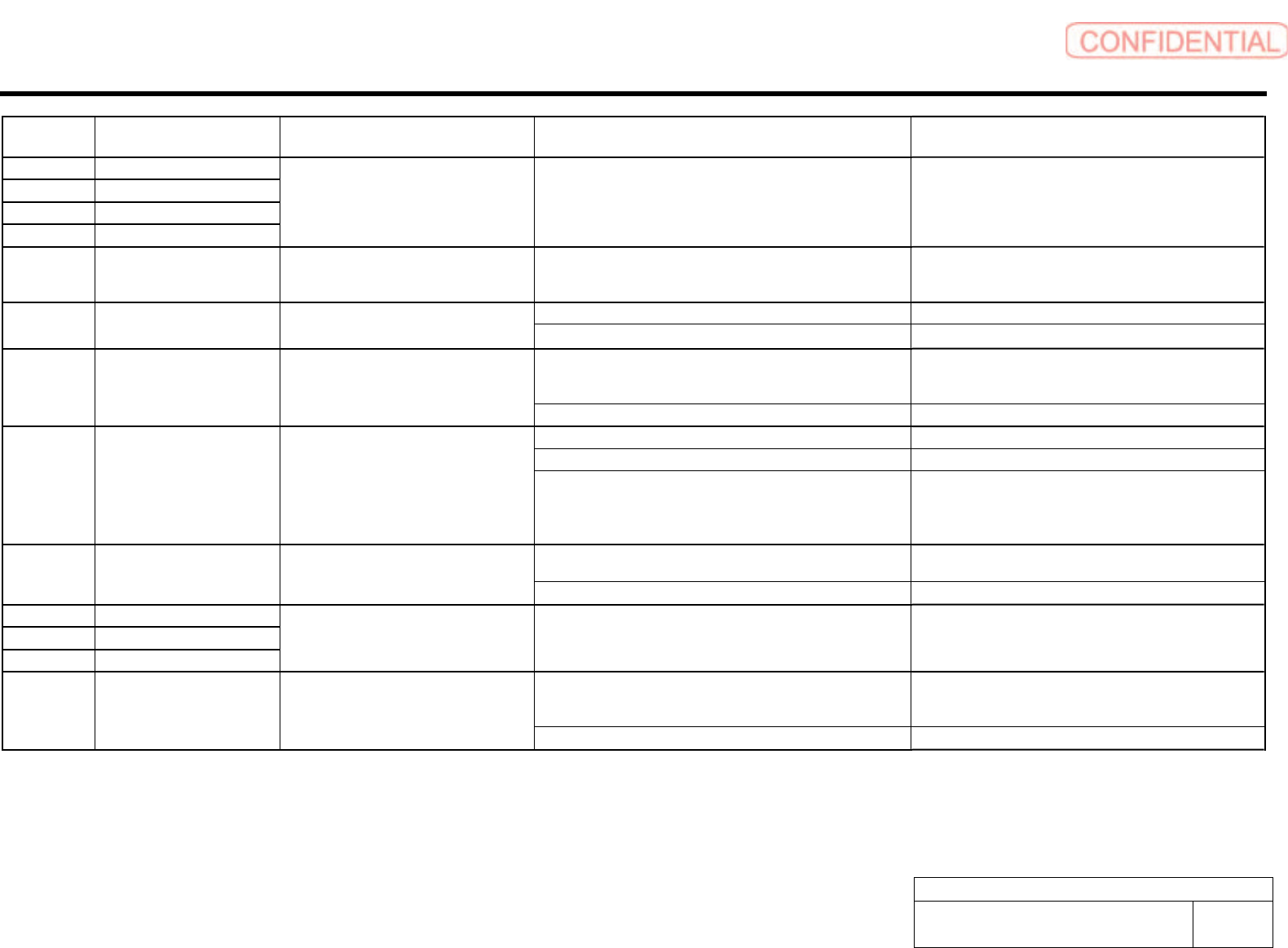
Alarm Name Situation at Alarm Occurrence Cause Corrective Actions
A.E00 COM Alarm 0
A.E01 COM Alarm 1
A.E02 COM Alarm 2
A.E07 COM Alarm 7
Occurred when the control power supply
was turned ON.
A SERVOPACK fault occurred. Replace the SERVOPACK.
A.E40 MECHATROLINK-II
Transmission Cycle Setting
Error
Occurred at MECHATROLINK-II
communications start.
Setting of MECHATROLINK-II transmission cycle is out of
specifications range.
Set the transmission cycle to proper value.
WDT data of host controller was not updated correctly. Update the WDT data at the host controller correctly. A.E50 MECHATROLINK-II
Synchronization Error
Occurred during MECHATROLINK-II
communications.
A SERVOPACK fault occurred. Replace the SERVOPACK.
WDT data of host controller was not updated correctly at the
synchronization communications start, and synchronization
communications could not start.
Update the WDT data at the host controller correctly.
A.E51 MECHATROLINK-II
Synchronization Failed
Occurred at MECHATROLINK-II
synchronization communications start.
A SERVOPACK fault occurred. Replace the SERVOPACK.
MECHATROLINK-II wiring is incorrect. Correct the MECHATROLINK-II wiring.
A SERVOPACK fault occurred. Replace the SERVOPACK.
A.E60 MECHATROLINK-II
Communications Error
Occurred during MECHATROLINK-II
communications.
MECHATROLINK-II data reception error occurred due to noise
interference.
Take measures against noise.
Check the MECHATROLINK-II communications cable and
FG wiring and take measures such as adding ferrite core on
the MECHATROLINK-II communications cable.
MECHATROLINK-II transmission cycle fluctuated. Remove the cause of transmission cycle fluctuation at host
controller.
A.E61 MECHATROLINK-II
Transmission Cycle Error
Occurred during MECHATROLINK-II
communications.
A SERVOPACK fault occurred. Replace the SERVOPACK.
A.EA0 DRV Alarm 0
A.EA1 DRV Alarm 1
A.EA2 DRV Alarm 2
Occurred when the control power supply
was turned ON or during operation.
A SERVOPACK fault occurred. Replace the SERVOPACK.
Parameter was changed by the digital operator or the personal
computer during MECHATROLINK-II communications.
Stop changing parameter using digital operator and do not
connect the personal computer during MECHATROLINK-II
communications.
A.ED0 Internal Command Error Occurred at MECHATROLINK-II
communications start or during operation.
A SERVOPACK fault occurred. Replace the SERVOPACK.
Alarm List for the Servo Pack "Sigma-III" Series (SGDS type)
BBGB-10101-01
Alarm List for the Servo Pack
"Sigma-III" Series (SGDS type)
SHEET
14/18
Alarm
Display
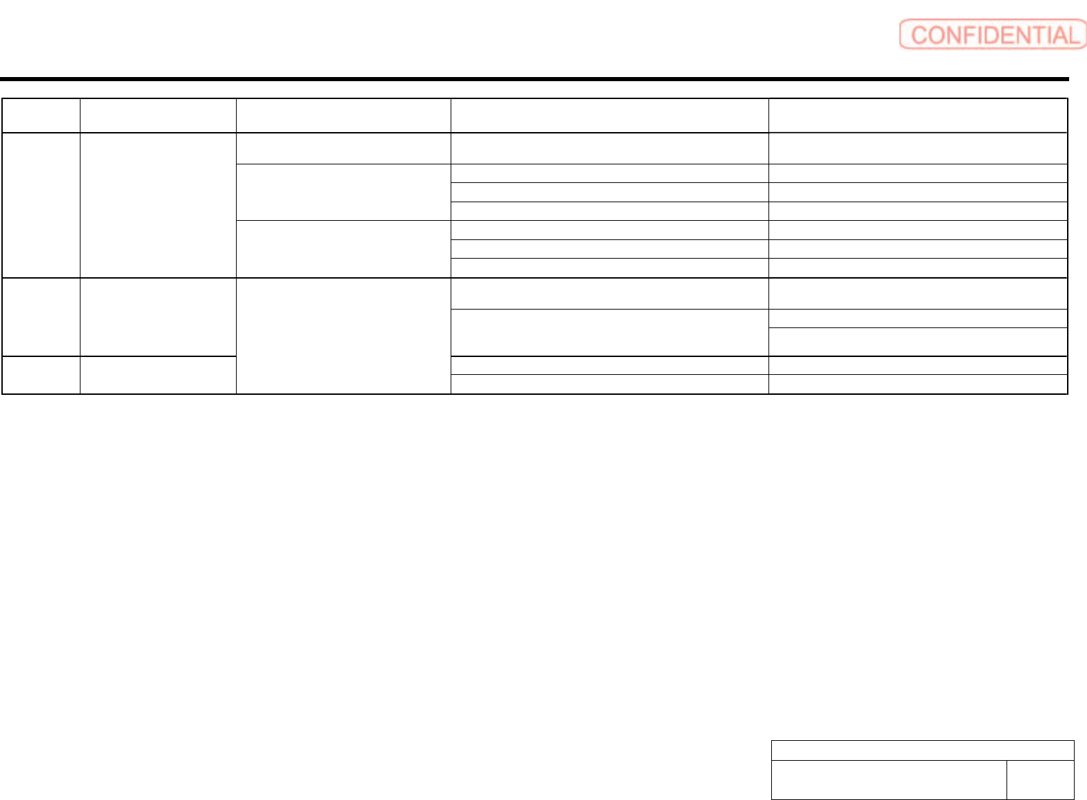
Alarm Name Situation at Alarm Occurrence Cause Corrective Actions
Occurred when the control power supply
was turned ON.
A SERVOPACK fault occurred. Replace the SERVOPACK.
The three-phase power supply wiring is incorrect. Correct the power supply wiring.
The three-phase power supply is unbalanced. Balance the power supply by changing phases.
Occurred when the main circuit power
supply was turned ON.
A SERVOPACK fault occurred. Replace the SERVOPACK.
The contact in three-phase power supply wiring is faulty. Correct the power supply wiring.
Three-phase power supply is unbalanced. Balance the power supply.
A.F10 Power Line Open Phase
Occurred when the servomotor was
running.
A SERVOPACK fault occurred. Replace the SERVOPACK.
The contact between the digital operator and the SERVOPACK
is faulty.
Insert securely the connector, or replace the cable.
Do not lay the cable near noise source.
CPF00 Digital Operator Transmission
Error 1
*1
The external noise interference occurred to the digital operator
or cable is faulty.(The digital operator cable is near noise
source)
Install digital operator far from noise source.
A digital operator fault occurred. Replace the digital operator. CPF01 Digital Operator Transmission
Error 2
*2
Occurred when the power supply was
turned ON with digital operator connected
or when connecting digital operator with
the power supply was turned ON.
A SERVOPACK fault occurred. Replace the SERVOPACK.
*1. This alarm occurs when the communications is still disabled five seconds after digital operator power supply is ON, or when digital operator communications disabled status stays while an option unit is
connected.
*2. This alarm occurs when digital operator received data error occurs consecutively five times, or when the state that digital operator receives no data from SERVOPACK for one second or more occurs
consecutively three times.