MAN00000772_SI-G200BB_SVCPDFA.pdf - 第608页
How to check RAS alarm BBGB-10102-01 How to check R A S alarm SHEET 1/4 How to check RAS alarm [Checking procedure on HI screen (alarm message)] 1 When any alarm messag e occurs, alarm message is displayed on the lef t l…
Alarm List for the Servo Pack "Sigma-III" Series (SGDS type)
BBGB-10101-01
Alarm List for the Servo Pack
"Sigma-III" Series (SGDS type)
SHEET
18/18
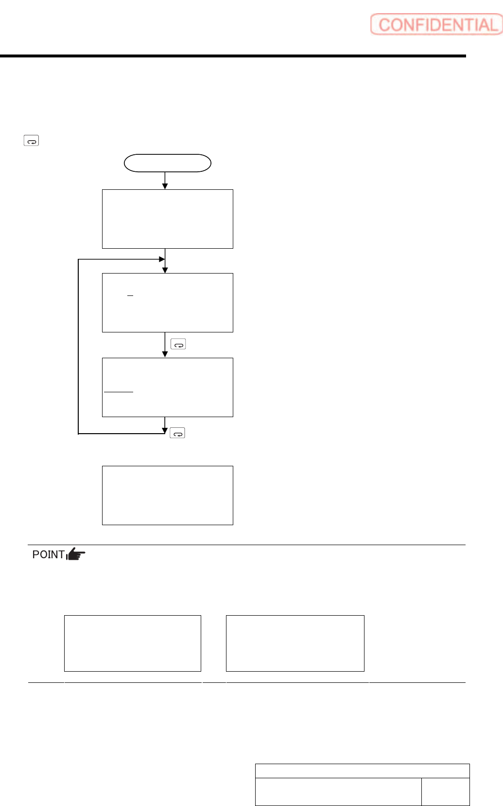
Switching Mode
Connect the digital operator to the SERVOPACK, and turn ON the power to the SERVOPACK.
The initial display appears, and then the Parameter/Monitor Mode display appears. Press the
MODE/SET
Key to change the mode. When an alarm occurs, the alarm display appears automatically.
File list loading
Please wait….
[Initial Display]
Displayed for two seconds
BB -PRM/MON-
Un000= 00000
Un002= 00000
Un008= 00000
Un00D=00000000
[Parameter/Monitor Modes]
MODE/SET
BB -FUNCTION-
Fn01E
Fn000
Fn001
Fn002
[Utility Function Mode]
MODE/SET
A.D00 -ALARM-
0:D00 00001207196
1:720 00000032651
2:511 00000009043
3:---
[Alarm Display]
When an alarm occurs, the alarm display appears
automatically.
If a communications error occurs between the SERVOPACK and digital operator, the following
communications error codes are displayed. These errors may be caused by incorrect connector
connection. Check the connection and correct. Then, turn the power OFF and ON. If the error
still occurs, replace the digital operator or the SERVOPACK.
CPF00
COM-ERR(OP&SV)
CPF01
COM-ERR(OP&SV)
* For detail of how to operate Digital Operator, refer to the “Instruction Manual for Sigma-III
Series SGMS/SGDS Digital Operator” in separate volume.
Power ON
How to check RAS alarm
BBGB-10102-01
How to check RAS alarm
SHEET
1/4
How to check RAS alarm
[Checking procedure on HI screen (alarm message)]
1 When any alarm message occurs, alarm
message is displayed on the left lower of the
HI screen.
2 Check how to recover the displayed alarm
on the [RAS alarm list] to recover the
equipment.
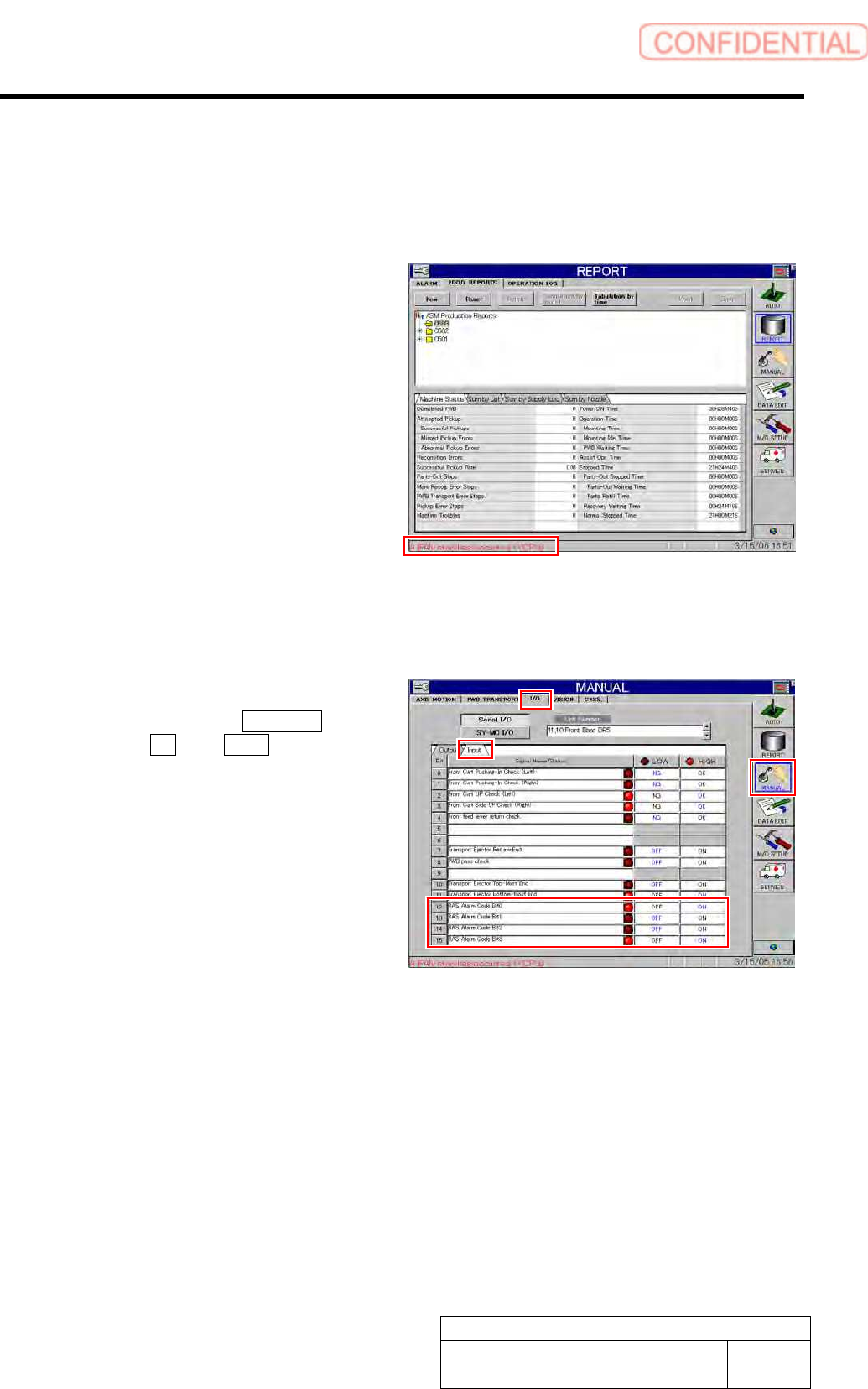
[Checking procedure on HI screen (bit display)]
1 Display I/O screen.
1. Click in an order of MANUAL
menuI/O tabInput tab.
I/O screen is displayed.
2 Check state of the displayed RAS alarm
codes bits 0 to 4.
As LED light-up means “1” and LED light-off means
“0”, bit display is “1001” on the left screen.
3 Check how to recover the alarm of this bit
display on the “RAS alarm list” to recover the
equipment.
How to check RAS alarm
BBGB-10102-01
How to check RAS alarm
SHEET
2/4
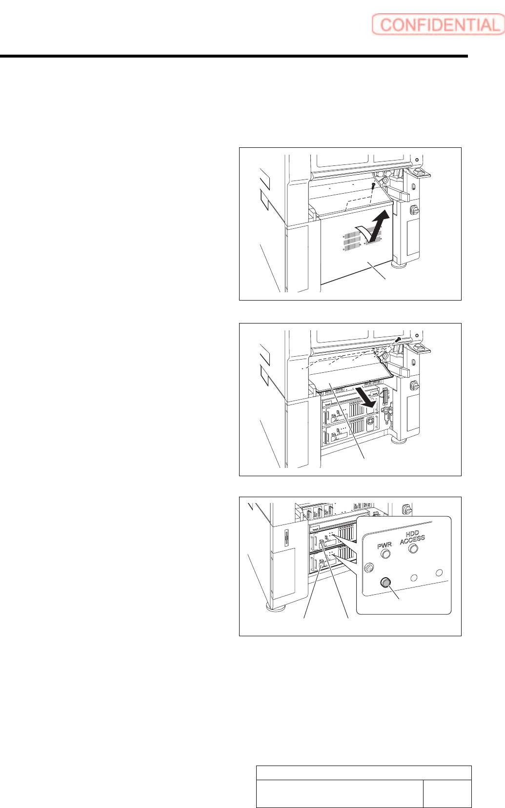
[Checking procedure on DR board]
When the HI screen is not displayed due to trouble on the equipment, check RAS alarm and
perform recovery operation according to the procedure described here.
1 Unscrew the 2 screws and remove the lower
panel on the front side of the unit.
Tilt the upper of the lower panel, and bring up as it is
to remove.
2 Unscrew the 4 screws and remove the
shooter on the front side of the unit.
3 Check that the RAS alarm lamp on the front
of the PC unit is lighting up.
It is possible to check that the presently occurred
alarm is RAS alarm by checking light-up status of the
RAS alarm lamp.
When RAS alarm occurs: Light-up
RAS
ALM
Shooter
PC unit (FRONT)
RAS alarm lamp
PC unit (REAR)
Lower panel