MAN00000772_SI-G200BB_SVCPDFA.pdf - 第609页
How to check RAS alarm BBGB-10102-01 How to check R A S alarm SHEET 2/4 [Checking procedure on DR board] When the HI scree n is not displayed due t o trouble on the e quipment, check RAS alarm and perform recover y opera…
How to check RAS alarm
BBGB-10102-01
How to check RAS alarm
SHEET
1/4
How to check RAS alarm
[Checking procedure on HI screen (alarm message)]
1 When any alarm message occurs, alarm
message is displayed on the left lower of the
HI screen.
2 Check how to recover the displayed alarm
on the [RAS alarm list] to recover the
equipment.
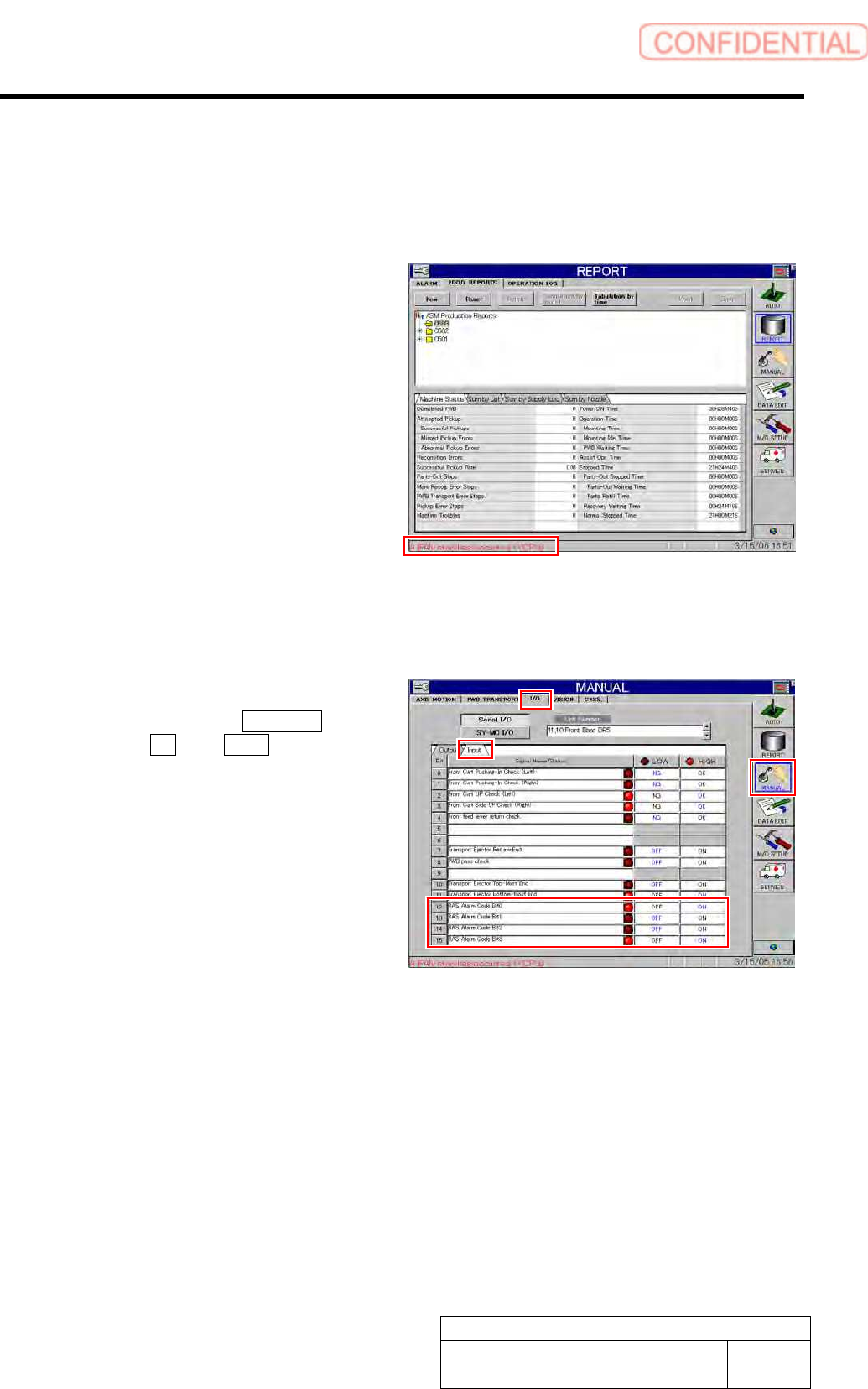
[Checking procedure on HI screen (bit display)]
1 Display I/O screen.
1. Click in an order of MANUAL
menuI/O tabInput tab.
I/O screen is displayed.
2 Check state of the displayed RAS alarm
codes bits 0 to 4.
As LED light-up means “1” and LED light-off means
“0”, bit display is “1001” on the left screen.
3 Check how to recover the alarm of this bit
display on the “RAS alarm list” to recover the
equipment.
How to check RAS alarm
BBGB-10102-01
How to check RAS alarm
SHEET
2/4
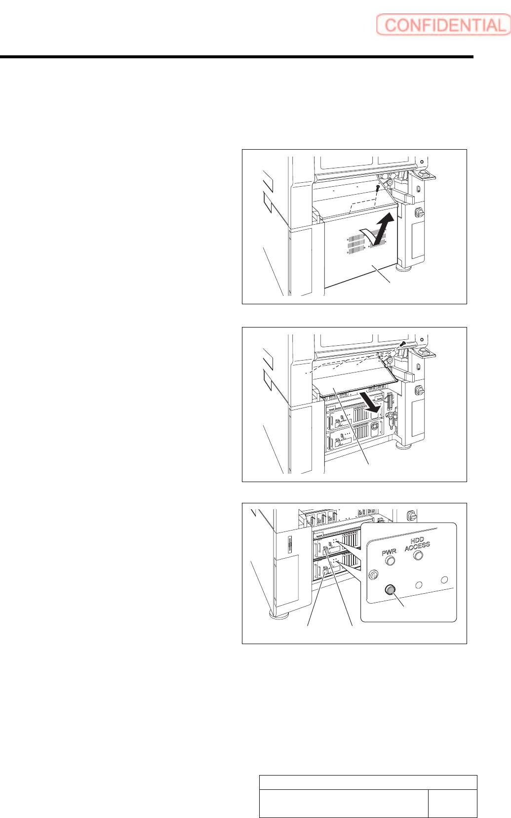
[Checking procedure on DR board]
When the HI screen is not displayed due to trouble on the equipment, check RAS alarm and
perform recovery operation according to the procedure described here.
1 Unscrew the 2 screws and remove the lower
panel on the front side of the unit.
Tilt the upper of the lower panel, and bring up as it is
to remove.
2 Unscrew the 4 screws and remove the
shooter on the front side of the unit.
3 Check that the RAS alarm lamp on the front
of the PC unit is lighting up.
It is possible to check that the presently occurred
alarm is RAS alarm by checking light-up status of the
RAS alarm lamp.
When RAS alarm occurs: Light-up
RAS
ALM
Shooter
PC unit (FRONT)
RAS alarm lamp
PC unit (REAR)
Lower panel
How to check RAS alarm
BBGB-10102-01
How to check RAS alarm
SHEET
3/4
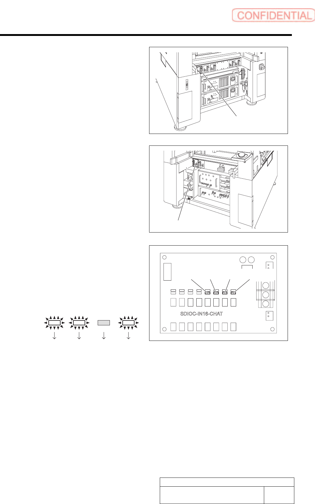
4 If the RAS lamp on the PC unit (front) is
lighting up, check light-up status of the LED
on the DR5-F board installed on the stand
on the front of the equipment.
5 If the RAS lamp on the PC unit (rear) is
lighting up, check light-up status of the LED
on the DR4-F board installed on the stand
on the back of the equipment.
If a shooter and a lower panel are installed on the back
of the equipment, remove them according to the same
procedure as removal of the shooter and the lower
panel on the front of the equipment.
6 Identify bit indication from light-up status of
LED13 to LED16 on the DR5-F or DR4-R.
1. LED light-up status is replaced with
bit display.
LED light-up means “1” and LED light-off
means “0”.
Example:
LED13
Bit:
LED14 LED15 LED16
1101
Bit display is arranged to be in an order of LED
16 to LED 13 from left, therefore, the bit display
in this example means “1011”.
7 Determine error code and error cause from the bit display and carry out processing for error
recovery.
For error cause and recovery method for every bit display and error code, refer to the following “RAS alarm list”.
LED13 LED14 LED15
LED16
DR5-F board
DR4-Rboard