MAN00000772_SI-G200BB_SVCPDFA.pdf - 第610页
How to check RAS alarm BBGB-10102-01 How to check R A S alarm SHEET 3/4 4 If the RAS lamp on the PC unit (front) is lighting up, check light-up statu s of the LED on the DR5-F board inst alled on the stand on the front o…
How to check RAS alarm
BBGB-10102-01
How to check RAS alarm
SHEET
2/4
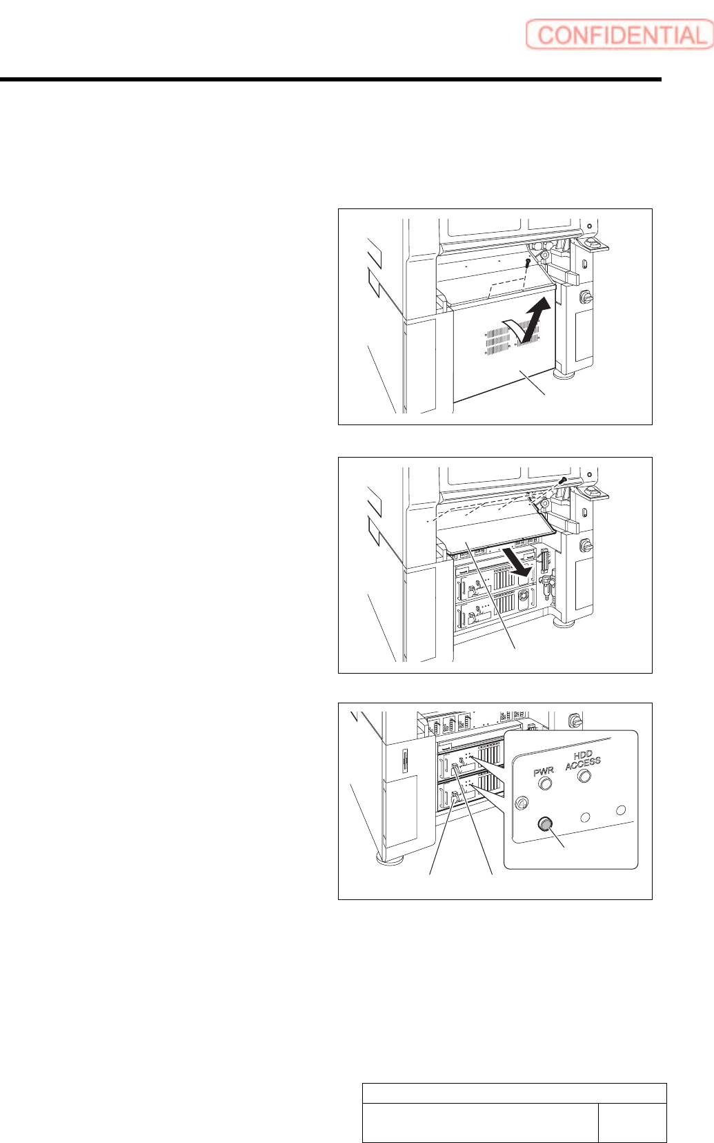
[Checking procedure on DR board]
When the HI screen is not displayed due to trouble on the equipment, check RAS alarm and
perform recovery operation according to the procedure described here.
1 Unscrew the 2 screws and remove the lower
panel on the front side of the unit.
Tilt the upper of the lower panel, and bring up as it is
to remove.
2 Unscrew the 4 screws and remove the
shooter on the front side of the unit.
3 Check that the RAS alarm lamp on the front
of the PC unit is lighting up.
It is possible to check that the presently occurred
alarm is RAS alarm by checking light-up status of the
RAS alarm lamp.
When RAS alarm occurs: Light-up
RAS
ALM
Shooter
PC unit (FRONT)
RAS alarm lamp
PC unit (REAR)
Lower panel
How to check RAS alarm
BBGB-10102-01
How to check RAS alarm
SHEET
3/4
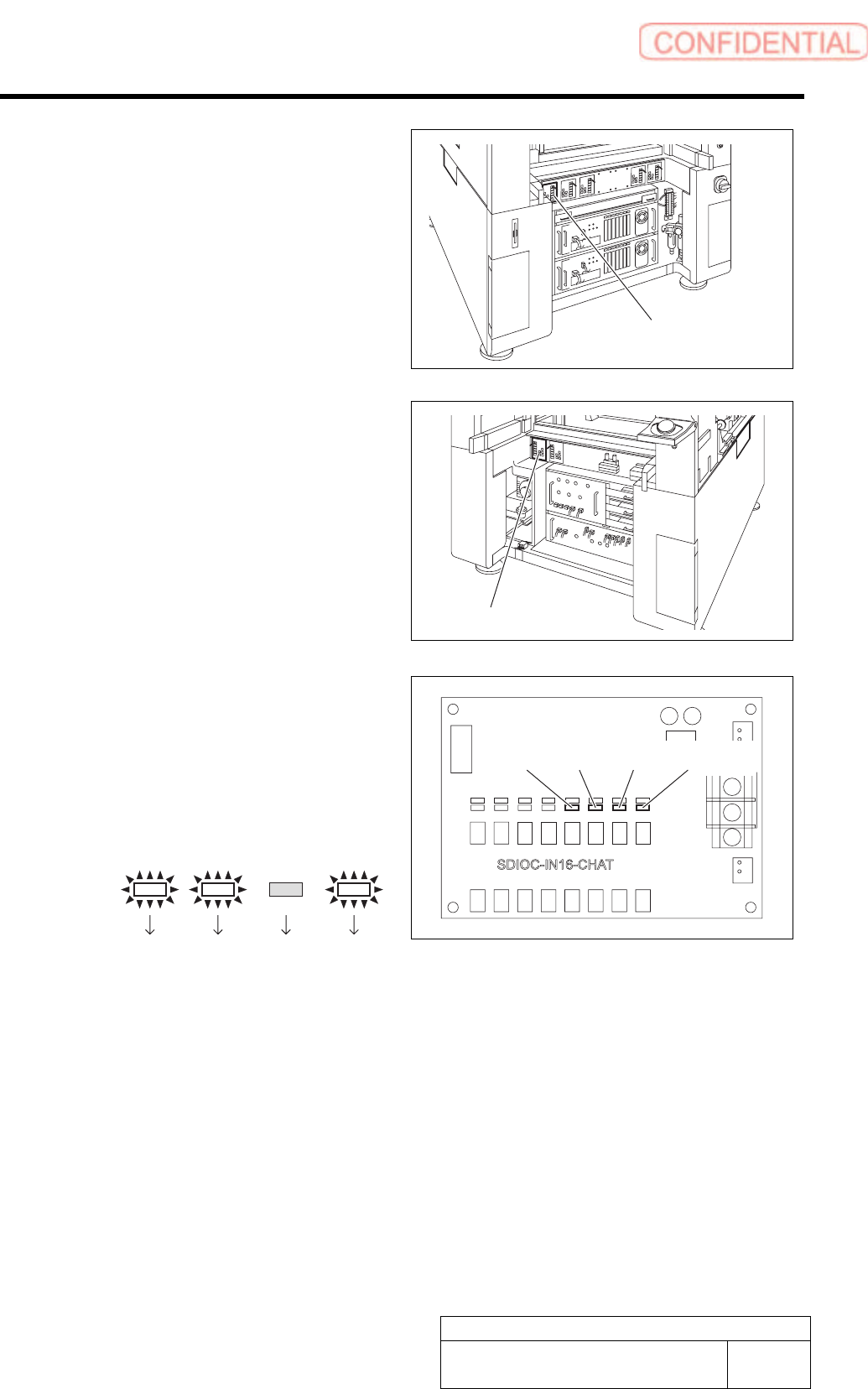
4 If the RAS lamp on the PC unit (front) is
lighting up, check light-up status of the LED
on the DR5-F board installed on the stand
on the front of the equipment.
5 If the RAS lamp on the PC unit (rear) is
lighting up, check light-up status of the LED
on the DR4-F board installed on the stand
on the back of the equipment.
If a shooter and a lower panel are installed on the back
of the equipment, remove them according to the same
procedure as removal of the shooter and the lower
panel on the front of the equipment.
6 Identify bit indication from light-up status of
LED13 to LED16 on the DR5-F or DR4-R.
1. LED light-up status is replaced with
bit display.
LED light-up means “1” and LED light-off
means “0”.
Example:
LED13
Bit:
LED14 LED15 LED16
1101
Bit display is arranged to be in an order of LED
16 to LED 13 from left, therefore, the bit display
in this example means “1011”.
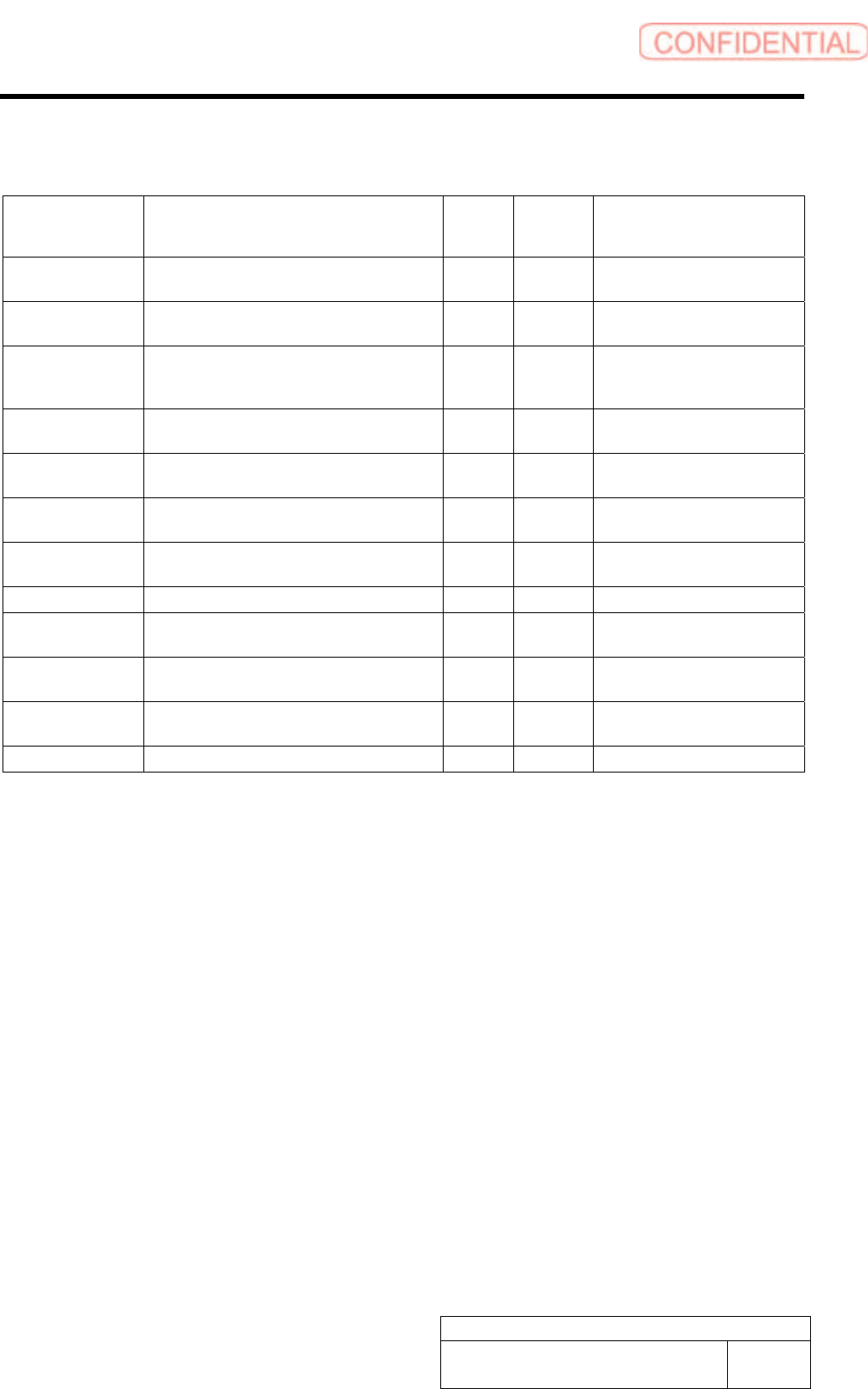
7 Determine error code and error cause from the bit display and carry out processing for error
recovery.
For error cause and recovery method for every bit display and error code, refer to the following “RAS alarm list”.
LED13 LED14 LED15
LED16
DR5-F board
DR4-Rboard
How to check RAS alarm
BBGB-10102-01
How to check RAS alarm
SHEET
4/4
[RAS Alarm list]
Alarm name Cause
Bit
display
Error
code on
HI
Recovery method
WDT alarm
VCPU failure, SDIO failure, ASM software does not
start up. Wiring for WDT is broken.
1111 F
Shut down by power off switch,turn
off main breaker, re-start up
Power ON error
PS_ON is not outputted from WCPU, and then ATX
power (PC power) is not turned ON.
0001 1
Check the cable, replace the WCPU
board
AC power error
ATX power detects AC power drop or power failure,
performs shutdown processing, turns OFF PC
power, and turns OFF machine control.
0010 2
Turn off main breaker, re-start up
after resetting AC power
DC voltage error 1
ATX power detects error of DC output voltage, PC
power is not turned ON, ATX power is failed
0011 3 Replace ATX power
DC voltage error 2
Vol tage of (ATX power+5V output) dropped, ATX
power is failed
0100 4 Replace ATX power
Temperature rise
error 1
Measurement value of temperature sensor on RAS
board exceeded set value. Filter is clogged.
0101 5 Clean the filter
Temperature rise
error 2
Measurement value of temperature sensor installed
in enclosure exceeded set value, filter is clogged
0110 6 Clean the filter
Power fan stop Fan in ATX power stopped, ATX power is failed 0111 7 Replace the ATX power
WCPU fan stop
Cooling fan for WCPU stopped, fan is failed, wire
broken
1000 8 Replace the fan
VCPU fan stop
Cooling fan for VCPU stopped, fan is failed, wire
broken
1001 9 Replace the fan
Enclosure fan stop
Any fan among four enclosure fans stopped, fan is
failed, wire broken
1010 A Replace the fan
Battery boltage drop ATX power detects battery terminal voltage drop 1011 B Charge or replace the battery
* When the RAS board backed up, the equipment is in rest without issuing any alarm.