MAN00000772_SI-G200BB_SVCPDFA.pdf - 第619页
4. Basic Operations of the Multifunctional Mounter TFGB-10101-0 1 SI-G200 (B Head) Overview SHEET 4/20 [Basic Operation] At regular time intervals, the refe rence mark on the fixed camera is recognized imme diately befor…
4. Basic Operations of the Multifunctional Mounter
TFGB-10101-01
SI-G200 (B Head) Overview
SHEET
3/20
4. Basic Operations of the Multifunctional Mounter
The multifunctional mounter picks up, recognizes, and mounts parts in the same way as SI-G Series mounters
(high-speed mounters). Described below are the operations, features, and points to note of the multifunctional
mounter.
4-1 Operations in Automatic Production
The flow of pickup, recognition, and mounting of parts in automatic production is shown below.
<Pickup>
Unless there are no special restrictions, such as the number of parts to be picked up simultaneously or
coexistence of Accuracy levels, continuous pickup is conducted according to the order of numbers defined
in machine model data.
When nozzle replacement is necessary during production, the nozzle replacement operation is conducted
before parts pickup.
<Recognition>
Recognition is conducted according to the recognition method specified by part data.
Multiple recognition operations may be conducted in the same path.
For each of parts set in the high-Accuracy mode, the operation from recognition to mounting is conducted.
Parts set in the high-Accuracy mode are recognized according to their mounting angles.
<Mounting>
Parts are mounted onto the coordinate positions specified by machine model data.
For each of parts set in the high-Accuracy mode, the operation from recognition to mounting is conducted.
When a pickup error or recognition error has occurred, an operation of disposing of parts is conducted after
this.
4-2 Fixed Camera Recognition Mark
Inflation or contraction of each section of the mounter due to temperature change causes the position of the
head to change during the movement of X and Y axes. Therefore, the change in the XY position needs to
be removed when parts are recognized.
During part recognition, change in the XY position due to inflation or contraction when parts move to
above a fixed camera causes an error in the posture or the position of parts. This influences the parts
mounting Accuracy of the mounter.
In order to remove this influence, when time specified in machine data has lapsed, the position of the
reference mark on the fixed camera is checked before parts are recognized by the camera, and the XY axis
position error when parts move to above the camera is compensated for.
The XY position when parts are mounted is removed when compensation with alignment mark recognition
is performed. Therefore, no other compensation needs to be performed.
4. Basic Operations of the Multifunctional Mounter
TFGB-10101-01
SI-G200 (B Head) Overview
SHEET
4/20
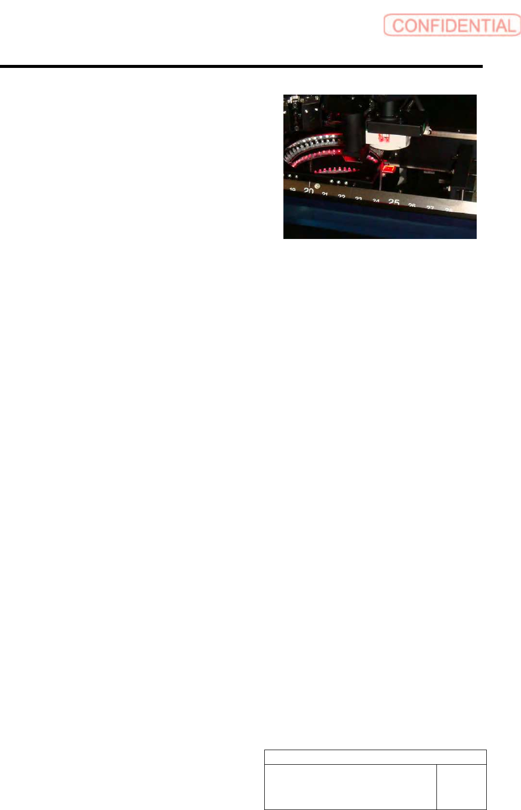
[Basic Operation]
At regular time intervals, the reference mark on the
fixed camera is recognized immediately before the
camera recognizes parts. After the position of a part
after its movement to above the fixed camera is
compensated for, based on the result of reference mark
recognition, the part is recognized.
[Operating Conditions]
1. When a specified time has lapsed during automatic production, the reference mark is recognized
immediately before parts are recognized.
2. When time has lapsed after motion stop, the reference mark is recognized immediately before part
recognition after automatic production restarts.
3. After power supply has restarted, the reference mark is recognized immediately before the first part
recognition.
4. The reference mark on the fixed camera is not recognized in the aging and simulation modes.
4-3 Pickup
[Basic Operation]
Unless there are any restrictions, parts move to the supply section according to the order defined in the
path of machine model data, and they are picked up continuously. When "Pickup Check" of part data has
been set to "ON," pickup check is carried out.
The operation of the pickup check differs, depending on part categories. For parts belonging to Category A,
pickup check is carried out with a pickup check camera used. For parts belonging to categories other than
A, pickup check is carried out with a pickup check sensor in the upper part of the fixed camera. The
number of parts that can be picked up simultaneously differs, depending on the part categories.
[Part Categories]
The multifunctional mounter can pick up larger-size parts that high-speed mounters cannot do by changing
its pickup check methods and recognition methods appropriately according to the sizes of parts.
As the result of that the scope of the sizes (width, length, and height) of parts to be handled has been
expanded, there are various operating conditions according to the sizes of parts to be handled, which are
determined by interference among parts when multiple parts are picked up simultaneously, interference
with a height recognition camera, conditions for nozzles to be used, etc.
In order to correspond with the characteristic of each part size, for the multifunctional mounter, "part
categories" defined by part sizes have been established. According to the part categories, the number of
parts that one head can pick up simultaneously, pickup check methods, RT and RN rotational restrictions,
recognition methods, and nozzle types change.
4. Basic Operations of the Multifunctional Mounter
TFGB-10101-01
SI-G200 (B Head) Overview
SHEET
5/20
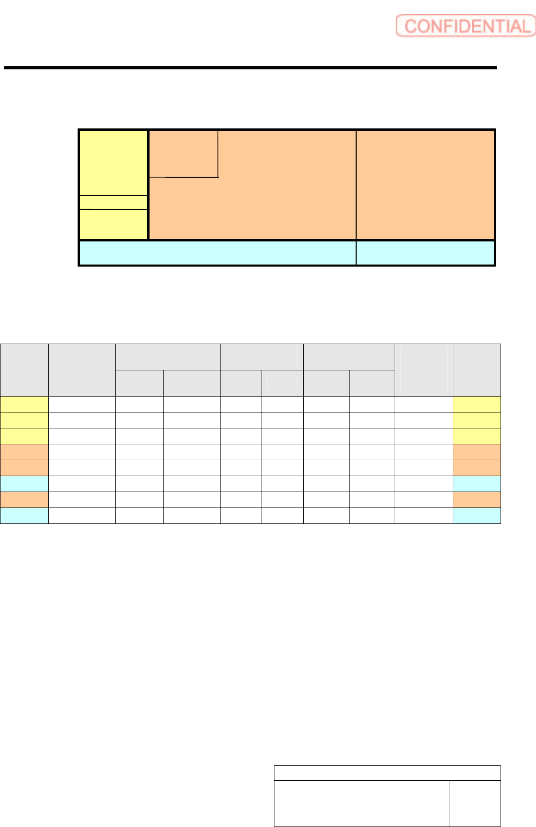
Part Category Table (Unit: mm)
Number of Parts That Can Be Picked Up Simultaneously, Characteristics,
and Restrictions According to Each Part Category
Pickup Check Method
Rotational
Restriction
Recognition Method
Category
Number of
Parts Picked
Up
Simultaneously
Camera
Presence
Sensor
RT RN Individual Global
Pickup
Check
Camera
Rising
Nozzle
Type
A 8 Ο × Absent Absent Ο Ο Unnecessary Standard
B1 8 × Ο Absent Absent Ο × Unnecessary Standard
B2 2 × Ο Absent Absent Ο × Unnecessary Standard
C 4 × Ο Absent Absent Ο × Unnecessary Long
D 2 × Ο Present Absent Ο × Unnecessary Long
E 2 × Ο Present Absent Ο × Unnecessary Short
F 1 × Ο Present Present Ο × Necessary Long
G 1 × Ο Present Present Ο × Necessary Short
- Number of parts that can be picked up simultaneously
Number of parts that can be picked up simultaneously with no interference with parts picked up by the
adjacent index after the RN axis has been rotated once and with the tape on the top of the part cassette.
- Rotational restriction
Restriction for preventing interference with the tape on the top of the cassette when the RT or RN axis is
rotated at the pickup position. When this rotational restriction is imposed, the RT axis is rotated only
counterclockwise. In addition, the RN axis cannot even be rotated.
- Pickup check camera rising
When relevant large parts are picked up, a pickup check camera rises.
Part long side length
0~10 ~20 ~40 ~100
~4.0
~10.5
~13
Part thickness
~6.5
~7.5
E
F
G
B1
B2
A
C
D