MAN00000772_SI-G200BB_SVCPDFA.pdf - 第623页
4. Basic Operations of the Multifunctional Mounter TFGB-10101-0 1 SI-G200 (B Head) Overview SHEET 8/20 4-4 Recognition There are three parts recognition methods: individual recognition, global recognitio n, and split rec…
4. Basic Operations of the Multifunctional Mounter
TFGB-10101-01
SI-G200 (B Head) Overview
SHEET
7/20
Recognition by a Pickup Check Camera
Pickup check on parts belonging to Category A (□10 mm, part thickness: 6.5 mm or less) is carried out
with a pickup check camera used. As shown in the basic operations, parts recognition by a pickup check
camera is conducted immediately after parts have been picked up.
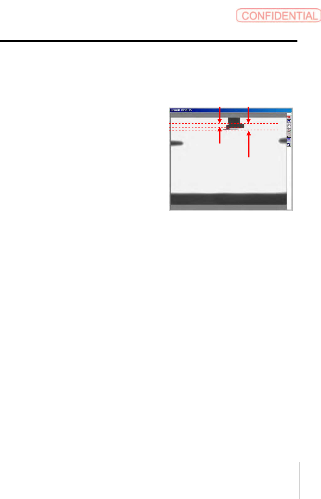
<Points to Note>
- Check on part thickness is carried out at the
position of the H axis being 0 mm.
- In parts recognition by a pickup check camera,
pickup check is carried out from the position
where the camera looks up at parts. Therefore,
measured thickness of parts is larger than the
actual thickness of them.
- Thin parts, even though they belong to Category
A, are not measured correctly in height and
thickness.
Recognition by a Part Presence Check Sensor
For parts belonging to categories other than A, pickup check is carried out not with a pickup check camera
but with a part presence check sensor used. Pickup check by a part presence check sensor is carried out
immediately before parts are recognized.
<Points to Note>
- Pickup check on parts with a width of less than 1 mm cannot be carried out. When parts are newly
created, “Pickup Check” is set to “OFF(0)” as default.(Even when “Pickup Check” has been set to
“ON(1),” pickup check is not carried out.)
- When pickup check is not carried with “Pickup Check” set to “OFF,” parts that have not been picked up
are not detected. Therefore, shortage of parts supplied from the cassette does not occur.
Actual part thickness
Measured thickness
4. Basic Operations of the Multifunctional Mounter
TFGB-10101-01
SI-G200 (B Head) Overview
SHEET
8/20
4-4 Recognition
There are three parts recognition methods: individual recognition, global recognition, and split recognition.
Which method can be used is determined according to part types based on shapes.
Recognition Methods Used According to Part Types Based on Shapes
Recognition Methods
Part Type Based on Shapes
Individual
Recognition
Global Recognition Split Recognition
Chip part O O ×
Lead part O O (partly*) O
BGA part O × O
Odd-shaped part (with leads) O × O
Odd-shaped part (without leads) O × O
Odd-shaped part (with balls) O × ×
- Global recognition can be set only for parts in Category A.
- When parts in the normal mode and ones in the high-Accuracy mode coexist in one path, the order in
which parts are picked up changes from the mount information setting. Parts with the same Accuracy
level as that of the first parts to be picked up are picked up and mounted first, and the remaining parts are
passed on to a recovery path.
- When globally recognized parts and individually recognized parts coexist in one path, either of global
recognition and individual recognition is conducted first. Which recognition is conducted first is
determined according to how the first parts to be mounted in the target path are recognized.
When the first parts to be mounted are individually recognized, individual recognition is conducted
first.
When the first parts to be mounted are globally recognized, global recognition is conducted first.
4-4-1 Individual Recognition
Picked up parts are recognized individually one by one. According to part sizes, you can select the wide or
Small view of the fixed camera. The H axis descends to the recognition height.
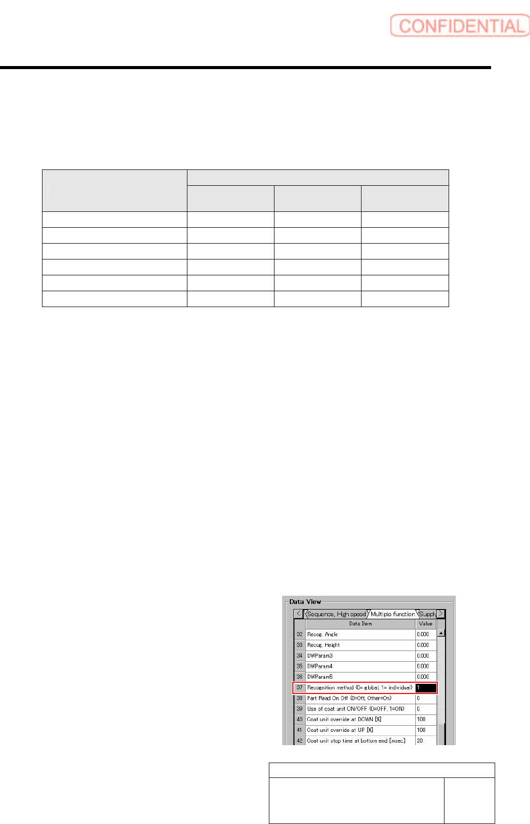
[Setting Method]
The setting for whether individual recognition
is conducted is configured for part data.
When you set “1” for “Recognition Method”
in “Sequence (Multifunction)” displayed after
selecting “Data Editing” and “Part
Management” in this order, individual
recognition is conducted.
4. Basic Operations of the Multifunctional Mounter
TFGB-10101-01
SI-G200 (B Head) Overview
SHEET
9/20
4-4-2 Global Recognition
Up to eight parts displayed in a picture taken by the Large view of the fixed camera are recognized. With
global recognition selected, the number of rotating operations of the turret and that of pictures taken are
decreased, thereby improving production takt time.
Global recognition is conducted with the center of the turret placed in the center position of the Large view
of the fixed camera.
The RT axis conducts global recognition with Index1 being below the H axis. At this time, recognition is
conducted with the H axis not descending.
[Scope of Application]
Global recognition can be conducted only for parts that meet the conditions for both part sizes and part
types based on shapes.
Global recognition can be conducted only for parts in Category A (□10 mm, part thickness: 6.5 mm or
less).
For the types (shapes) of parts for which global recognition can be conducted, see the table below.
Parts for Which Global Recognition Can Be Conducted and Other Conditions
Part Types Based on Shapes
Whether Recognition
Can Be Conducted
Other Conditions
Chip part O -
Lead part O (partly)
The number of lead sets is less than three, the number of leads
per set is less than five, and the width of a lead is 0.3 mm or
more at the same time.
BGA part × -
Odd-shaped part (with leads) × -
Odd-shaped part (without leads) × -
Odd-shaped part (with balls) × -
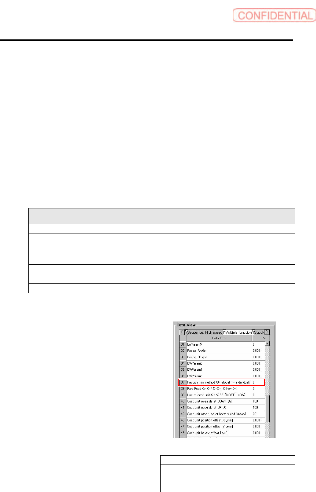
[Setting Method]
The setting for whether global recognition is
conducted is configured for part data.
When you set “0” for “Recognition Method” in
“Sequence (Multifunction)” displayed after
selecting “Data Editing” and “Part Management”
in this order, global recognition is conducted.