MAN00000772_SI-G200BB_SVCPDFA.pdf - 第63页
SHEET Su pply section of cassette specification is different from that of tr a y specification in optical axis p osi ti on of area sen sor . Be car eful of sensor mo un ting p os iti on and ho le p osi ti on for jig befo…
Install Tray Unit (Including machine modification)
SHEET
23/73
WKGB-10104-03
Installing Tray Unit
(Including machine modification)
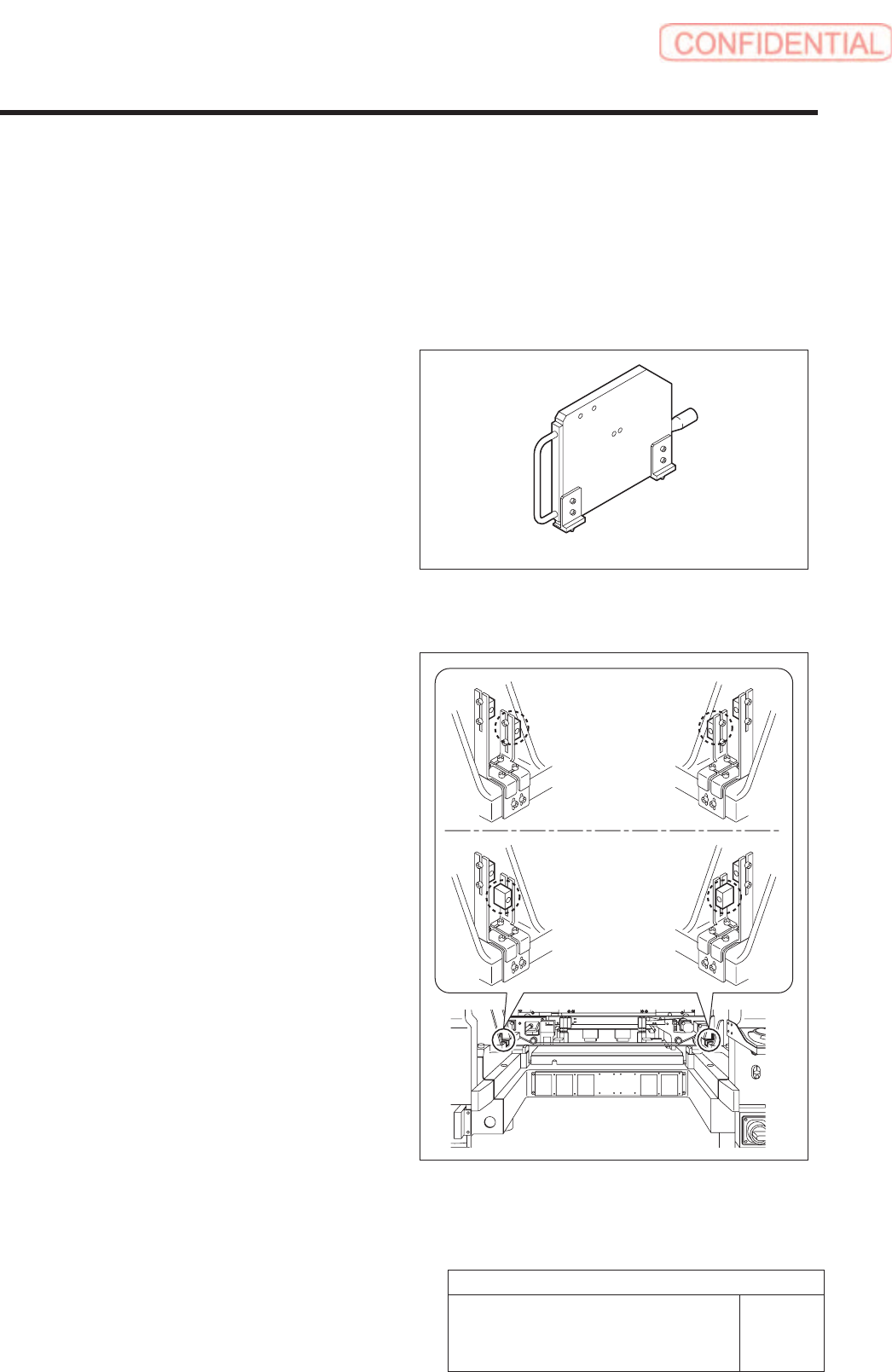
3 Loosen the 2-CP4x8 to remove the area
sensor.
4 Fix the cassette table with the
4-CP10x40.
5 Install the area sensor to the previous position.
1.
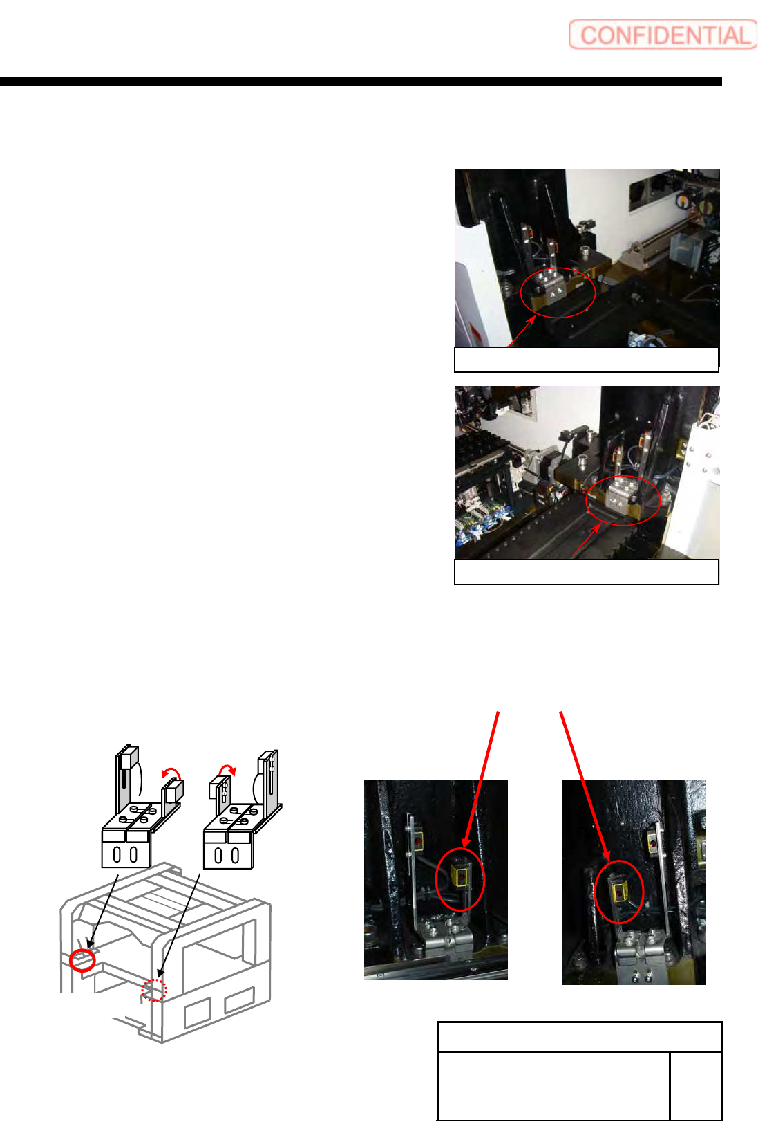
Replace Beam sensor as shown in the figure below (364DT, 364DR) .
Sensor bracket on right side
Sensor bracket on left side
BL
BR
364UT
364DT
364UR
364DR
(Rear)
SHEET
Supply section of cassette specification is different from that of tray specification in optical axis
position of area sensor. Be careful of sensor mounting position and hole position for jig before
carrying out optical axis adjustment.
[Necessary jigs]
• Optical axis adjustment jig
[Procedure]
1. Check area sensor mounting position.
Cassette specification is different from tray
specification in area sensor mounting method.
Check that the area sensor is mounted so as to be
suitable for the specification.
Optical axis adjustment jig
Cassette
specification
Tray specification
Install Tray Unit (Including machine modification)
24/73
WKGB-10104-03
Installing Tray Unit
(Including machine modification)
6 Area Sensor Optical Axis Adjustment

SHEET
2 Turn ON power for the unit to check that the
floodlighting area sensors are installed on
the right side of the unit.
3. Set the optical axis adjustment jig to the
position of supply No. 101.
1 ) Check that the replacing carrier has
been raised.
2 ) Set the optical axis adjustment jig on
the cassette table of supply No.101.
There should be no gap between the optical axis
adjustment jig and the cassette table.
4. Adjust mounting position of the area sensor
so that optical axis of the area sensor
passes through center of the hole on the
optical axis adjustment jig.
The right figure describes how to adjust the area
sensor on the right side as an example. Also adjust
position of the area sensor on the left side in the same
way.
1 ) Loosen the mounting bolts for the area
sensor to adjust up and downward
positions.
2 ) Loosen the cap screw on the lower side
of the bracket to adjust forward and
backward position of the area sensor.
Rear
Front
Optical axis
adjustment jig
Area sensor
Optical axis
25/73
WKGB-10104-03
Installing Tray Unit
(Including machine modification)
Install Tray Unit (Including machine modification)
.