MAN00000772_SI-G200BB_SVCPDFA.pdf - 第631页
5. Optional TFGB-10101-0 1 SI-G200 (B Head) Overview SHEET 16/20 [Setting for the Number of Remaining Part s When a Machine Is S witched to Another] - Follow th e setting for “Specified V alue for Remaining Parts When Ma…
5. Optional
TFGB-10101-01
SI-G200 (B Head) Overview
SHEET
15/20
5. Optional
5-1 Tray Changer (Optional)
The tray changer can supply parts with a thickness of up to 13 mm. The operation of part pickup,
recognition, and mounting in this order is the same as the production operation of SI-F209 that uses a tray
unit.
Tray pallets housed in the VU and VL axes are pulled out to the supply position by the S axis pull-in pin.
While pallets are supplied, the V-axis shutter opens.
The V axis performs a follow-up operation so that the upper and lower trays do not interfere with each
other. When the machine is set up, the distance between the upper and lower trays is set.
[Specifications of the Tray Operation When Parts Are Picked Up]
- When parts are picked up, the pickup position of the Y axis of the head is fixed, and the pull-out position
of the S axis changes according to the number of remaining parts. However, there are pickup offsets of
parts (Y axis), the Y axis of the head moves according to the amount of offsets.
- After the tray changer has picked up parts supplied from a tray, it houses its tray pallets immediately so
that it can pick up parts from another tray successively.
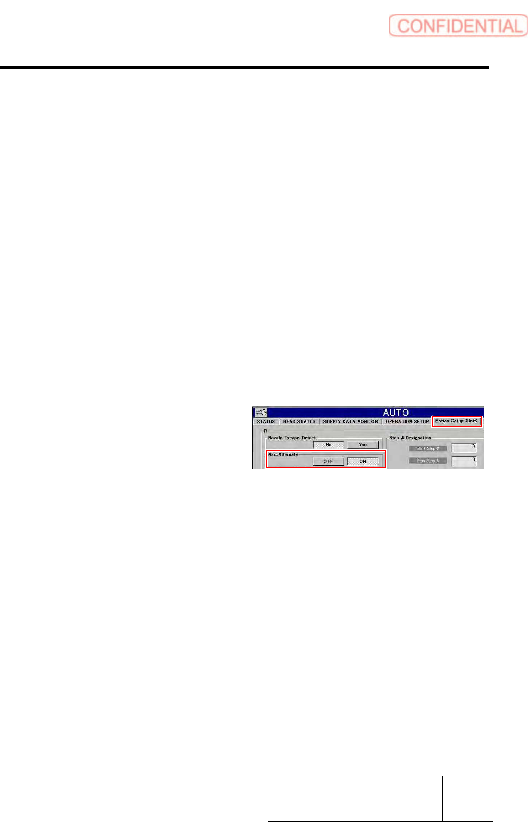
[Part Replacement during Automatic Operation]
- When “Alternate Tray Axis” is set to “ON”
in “Motion Setup (Unit)” displayed after
“Automatic Production” has been selected,
parts can be replaced during automatic
production. When shortage of parts has
occurred on the upper or lower tray unit,
parts are replaced on one tray unit while
automatic production continues on the other.
<Points to Note>
Only can set either one of “Axis alternate / ON” and “Parts out mode / continue”.
5. Optional
TFGB-10101-01
SI-G200 (B Head) Overview
SHEET
16/20
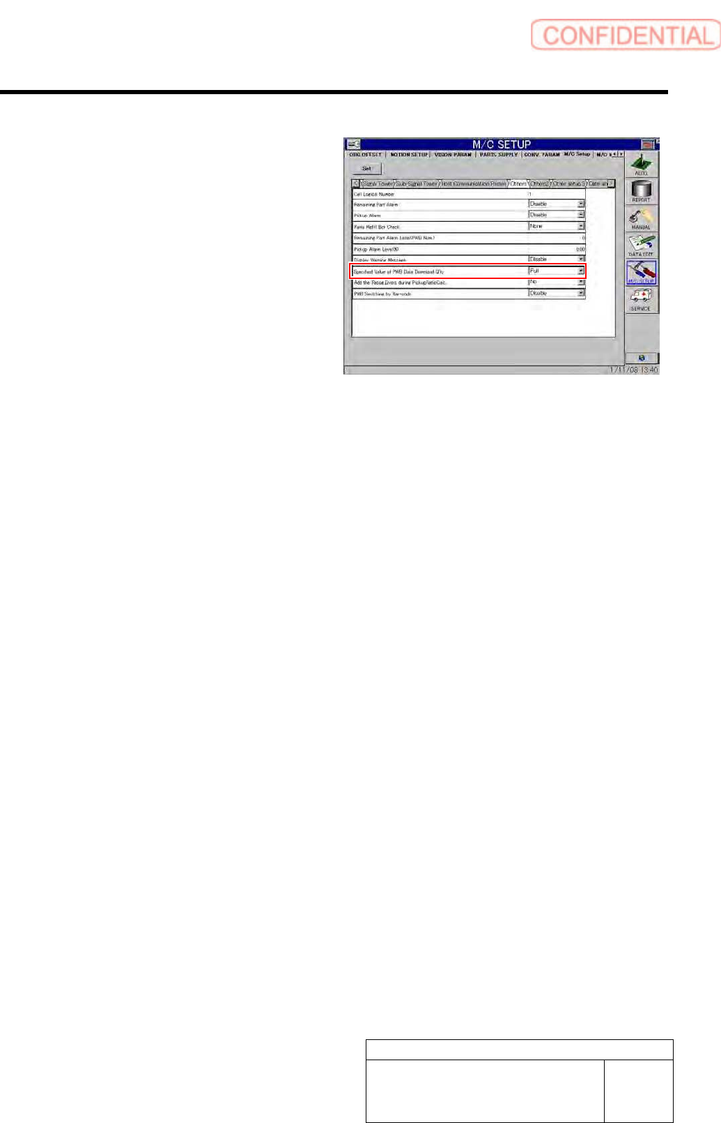
[Setting for the Number of Remaining Parts When a Machine Is Switched to Another]
- Follow the setting for “Specified Value for
Remaining Parts When Machine Model
Data Is Downloaded” in “Other Settings”
displayed after “Machine Setup” and
“Equipment Setup” have been selected in
this order.
However, when the supply section
information (pitch X and Y, origin X and Y,
and quantity X and Y) of the supply section
of the switched machine is the same as that
of the original machine, it is judged that
there was no change in the supply section,
and the number of remaining parts is kept as
it is by the switched machine.
5. Optional
TFGB-10101-01
SI-G200 (B Head) Overview
SHEET
17/20
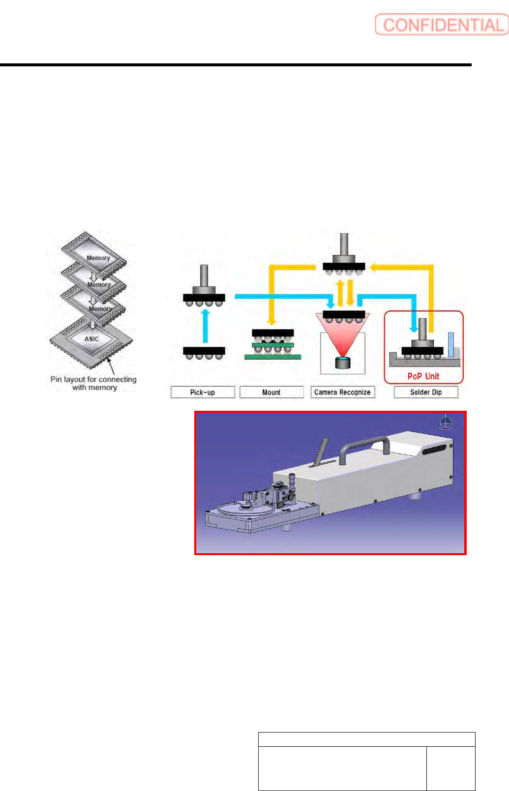
5-2 POP / Package On Package (Optional)
When POP (optional) is used, parts can be mounted on a part mounted on a PWB. In order to mount parts
with POP used, it is necessary to install the cassette interface and dip unit.
[Basic Operation]
According to part data, apply solder to a picked up part, and then mount the part on the coordinate position
specified by machine model data. It is necessary to install the solder application unit in the supply section.
Time for part recognition to be conducted needs to be selected among “before solder application,” “after
solder application,” and “before and after solder application.”
<Recognition of Alignment Marks of POP Parts>
- Alignment marks of the second and later parts mounted on the first part are recognized at the beginning
of the path in which POP parts are mounted. This recognition is excluded from the alignment mark
recognition when a PWB is carried in.
<Mounting of POP Parts>
- With multiple POP parts picked up, solder can be applied to each of the parts.
- POP parts that are mounted on the same location in one path cannot be picked up.
- POP parts are mounted in the high-Accuracy mode.
- For solder application operation, the data registered in motion data of part data is used.