MAN00000772_SI-G200BB_SVCPDFA.pdf - 第633页
5. Optional TFGB-10101-0 1 SI-G200 (B Head) Overview SHEET 18/20 - When part recognit ion has been conduct ed before flu x application, c ompensation of al igning the cent er position of a part when it moves to the d i p…
5. Optional
TFGB-10101-01
SI-G200 (B Head) Overview
SHEET
17/20
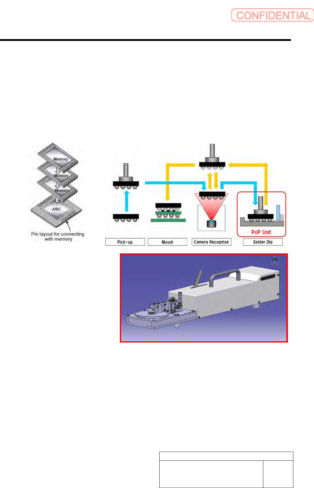
5-2 POP / Package On Package (Optional)
When POP (optional) is used, parts can be mounted on a part mounted on a PWB. In order to mount parts
with POP used, it is necessary to install the cassette interface and dip unit.
[Basic Operation]
According to part data, apply solder to a picked up part, and then mount the part on the coordinate position
specified by machine model data. It is necessary to install the solder application unit in the supply section.
Time for part recognition to be conducted needs to be selected among “before solder application,” “after
solder application,” and “before and after solder application.”
<Recognition of Alignment Marks of POP Parts>
- Alignment marks of the second and later parts mounted on the first part are recognized at the beginning
of the path in which POP parts are mounted. This recognition is excluded from the alignment mark
recognition when a PWB is carried in.
<Mounting of POP Parts>
- With multiple POP parts picked up, solder can be applied to each of the parts.
- POP parts that are mounted on the same location in one path cannot be picked up.
- POP parts are mounted in the high-Accuracy mode.
- For solder application operation, the data registered in motion data of part data is used.
5. Optional
TFGB-10101-01
SI-G200 (B Head) Overview
SHEET
18/20
- When part recognition has been conducted before flux application, compensation of aligning the center
position of a part when it moves to the dip unit position with the center position of the application is
performed.
- When it has been judged by the pickup check after application that there is no part, parts may remain in
the dip unit, and, therefore, the process stops as an error.
- When a recognition error has occurred for parts for which pickup check is not conducted after
application, it is assumed that parts remain in the dip unit, the process stops as an error.
- When handling data on machine models on which POP parts are mounted, you cannot continue
automatic production while shortage of parts occurs. (If you change the setting, it will be ignored.)
- Simulation and aging modes can be executed without installing the dip unit.
- The retract position of the head when an error has occurred in the dip unit is the same as the standby
position when shortage of parts has occurred.
[Items to Be Set]
ON/OFF of use of the
application unit
It is set whether the application unit is used when parts are mounted.
ON: The application unit is used.
OFF: The application unit is not used.
Override during the H axis
descent for the application unit
The override is set when the H axis descends. (The setting for the overall override
is applied to this item.)
Setting range: 1 to 100 [%]
Override during the H axis
ascent for the application unit
The override is set when the H axis ascends. (The setting for the overall override
is applied to this item.)
Setting range: 1 to 100 [%]
Descent stationary time for the
application unit
The stationary time of the head at the height of application is set.
Setting range: 0 to 32,767 [msec]
Application unit position
offset X
The amount of fine adjustment of the application position in the X direction is set.
Setting range: -9999.999 to 9999.999 [mm]
Application unit position
offset Y
The amount of fine adjustment of the application position in the Y direction is set.
Setting range: -9999.999 to 9999.999 [mm]
Application unit height
offset
The thickness of solder printed in the application unit is entered.
Setting range: -9999.999 to 9999.999 [mm]
Flux thickness The push-in amount when solder is applied is entered.
Setting range: 0 to 9999.999 [mm]
Recognition-conducting timing
for the application unit
Part recognition timing when the application unit is used is selected.
0: Parts are recognized before flux is applied.
1: Parts are recognized after flux is applied.
2: Parts are recognized before and after flux is applied.
5. Optional
TFGB-10101-01
SI-G200 (B Head) Overview
SHEET
19/20
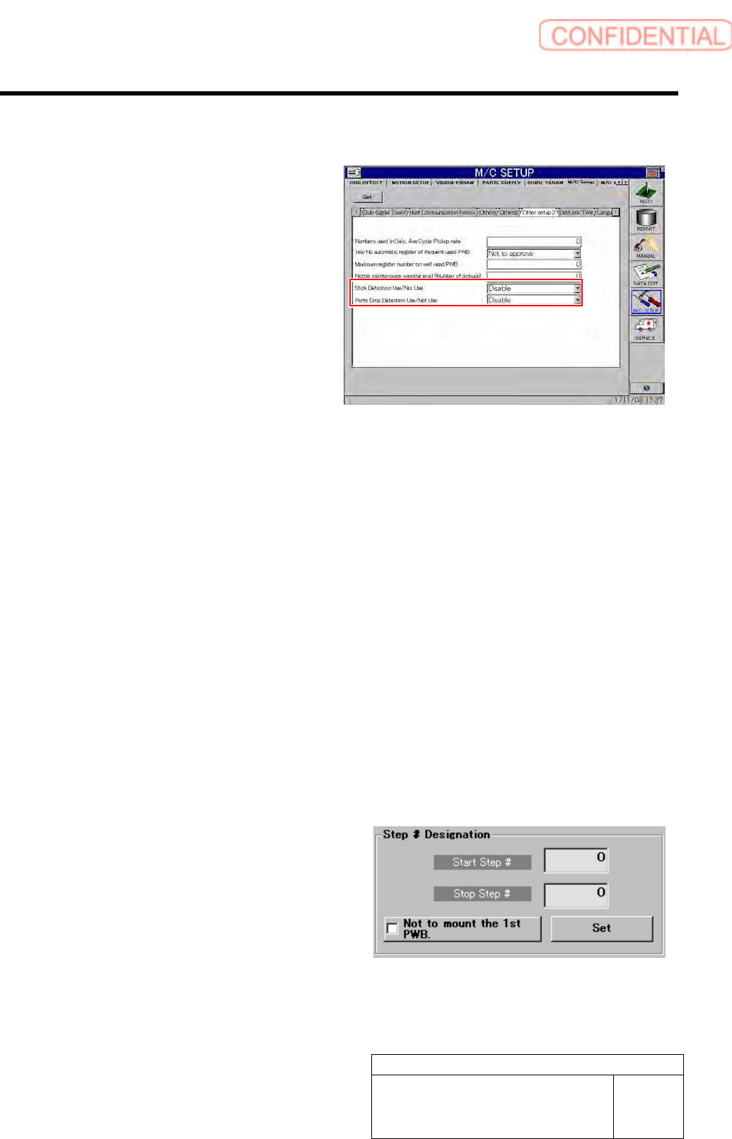
5-3 Detection of Adhesion and Missing Parts (Optional)
You can set whether each of adhesion
detection and missing part detection options
is used.
You can set whether to use adhesion
detection and missing part detection in
“Other settings 3” displayed after “Machine
Setup” and “Equipment Setup” have been
selected in this order.
5-3-1 Adhesion Detection
[Adhesion Detection Operation]
The state of the nozzle tip after the last part to be mounted has been mounted is checked by the pickup
check camera.
This check is conducted at one of the moments shown below.
- When a nozzle moves to the nozzle replacement position for nozzle replacement
- At the beginning of the pickup sequence
- When a part to be disposed of moves to the disposal position
- Disposal index after a part has been disposed of
When the difference between the nozzle recognition result and the check result is larger than the value set
in “nozzle_lib .ini,” it is judged that adhesion has been detected, and the process stops as an error.
In the same way as the conditions for part thickness check, adhesion detection can be performed only for
parts that can be recognized by the pickup check camera (parts in Category A).
[Treatment When Adhesion Is Generated]
- Remove a part on which adhesion has been
generated from the nozzle.
- For the step on which adhesion has been
generated, see the parameter value of the alarm.
- For a part on which adhesion has been
generated, specify the start and stop steps in
[Step Specification] on the “Motion Setup
(Unit)” screen displayed after “Automatic
Production” has been selected, and mount a part
again.