MAN00000772_SI-G200BB_SVCPDFA.pdf - 第645页
F axis movable part RPGB-10101-01 F A xis Belt Replacement Proced ure SHEET 6/9 3 Install two pulley shaf ts to the main fram e assembly . Apply Lock T ight 242 to th e eight locations on th e outer circumfelence of the …
F axis movable part
RPGB-10101-01
F Axis Belt Replacement Procedure
SHEET
5/9
[Installment]
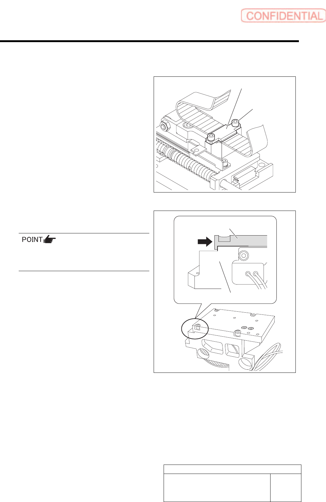
1 Fasten 2-C3x8 screws to fix the belt by the
joint.
Clamping torque : 98cN.m
Lock Tight 242 is applied to the screw.
2 Fasten 4-C4x10 screws and install the parts
feed assembly to the main frame.
Press the parts feed assembly against the main
frame assembly.
Clamping torque : 196cN.m
2-C3x8
Joint
Parts feed assembly
Main frame
F axis movable part
RPGB-10101-01
F Axis Belt Replacement Procedure
SHEET
6/9
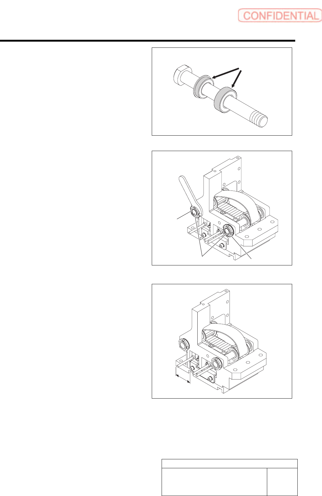
3 Install two pulley shafts to the main frame
assembly.
Apply Lock Tight 242 to the eight locations on the
outer circumfelence of the Lock Tight 242.
4 Fasten the U nut to fix the pulley shaft.
5 When the sensor bracket has been
removed, install the sensor bracket 26.5 mm
away from the frame end as shown in the
figure.
Lock Tight
Pulley shaft
U nut
U nut
26.5mm
F axis movable part
RPGB-10101-01
F Axis Belt Replacement Procedure
SHEET
7/9
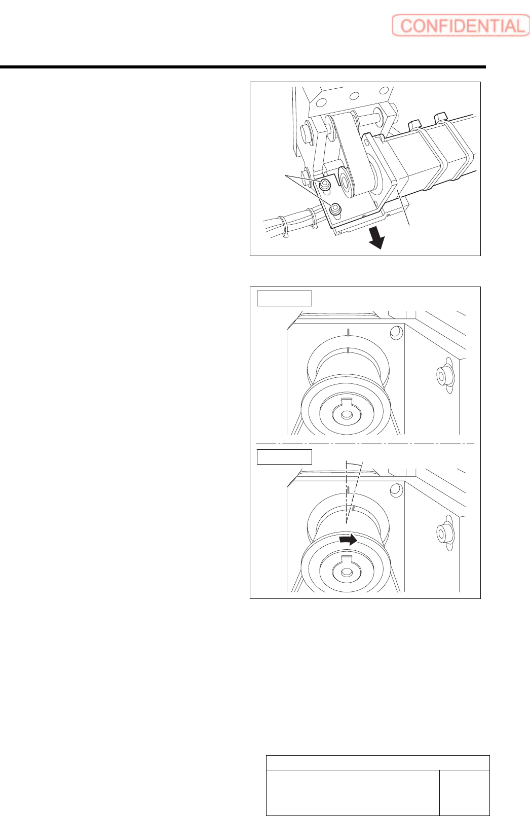
6 Fasten 2-C4x10 screws to install the motor
assembly to the main frame assembly.
Temporary fastening.
7 Hold up the motor bracket and temporarily
fasten the 2-C4x10 screws.
8 Check the position of the match mark for
motor Z-phase.
1. Turn around the pulley in the arrow
direction as shown in Fig. 2 and check
that discrepancy with the match mark
is about 15 degrees when the pulley hit
the at the mechanical end.
If the position doesn’t match the above
condition, decrease The tension temporarily to
change the position by turning around the
pulley.
(A ridge of the belt is about 15 degrees.)
2-C4x10
Motor assembly
Figure 1
Figure 2
15 degrees