MAN00000772_SI-G200BB_SVCPDFA.pdf - 第647页
F axis movable part RPGB-10101-01 F A xis Belt Replacement Proced ure SHEET 8/9 9 Adjust tension of the belt. 1. Install the tension JIG. 2. Pull the motor bracket after fast ening C3x12 screws to adjust tension. T e nsi…
F axis movable part
RPGB-10101-01
F Axis Belt Replacement Procedure
SHEET
7/9
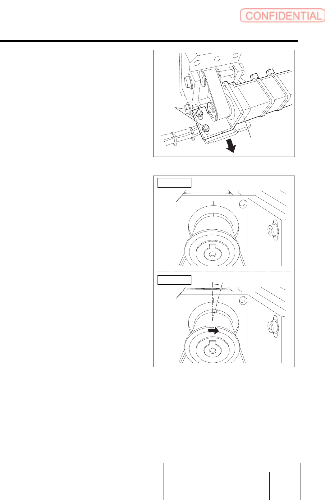
6 Fasten 2-C4x10 screws to install the motor
assembly to the main frame assembly.
Temporary fastening.
7 Hold up the motor bracket and temporarily
fasten the 2-C4x10 screws.
8 Check the position of the match mark for
motor Z-phase.
1. Turn around the pulley in the arrow
direction as shown in Fig. 2 and check
that discrepancy with the match mark
is about 15 degrees when the pulley hit
the at the mechanical end.
If the position doesn’t match the above
condition, decrease The tension temporarily to
change the position by turning around the
pulley.
(A ridge of the belt is about 15 degrees.)
2-C4x10
Motor assembly
Figure 1
Figure 2
15 degrees
F axis movable part
RPGB-10101-01
F Axis Belt Replacement Procedure
SHEET
8/9
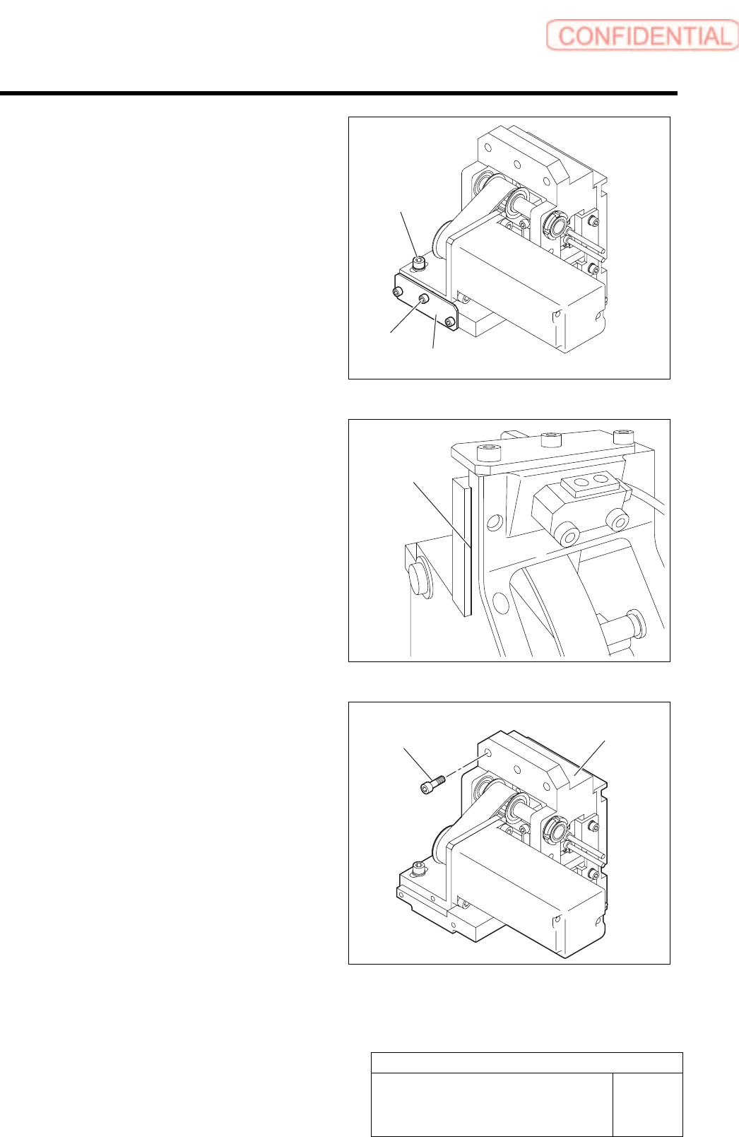
9 Adjust tension of the belt.
1. Install the tension JIG.
2. Pull the motor bracket after fastening
C3x12 screws to adjust tension.
Tension meter : UNITTA U-505
Specification : 70~85N
WEIGHT:2.5gf/m
WIDTH:15mm
SPAN:40mm
3. Fasten 2-C4x10 with no gap between
the motor bracket and the main frame.
Clamping torque : 196cN.m
10 Push up the bracket that fixes the cable bear
and fasten 3-C5x15 screws to install it to the
F axis unit.
11 Insert the motor power line and the encoder
line to the relay plate.
Tension JIG
C3x12
2-C4x10
Confirm there
is no gap.
3-C5x15
F axis unit
F axis movable part
RPGB-10101-01
F Axis Belt Replacement Procedure
SHEET
9/9
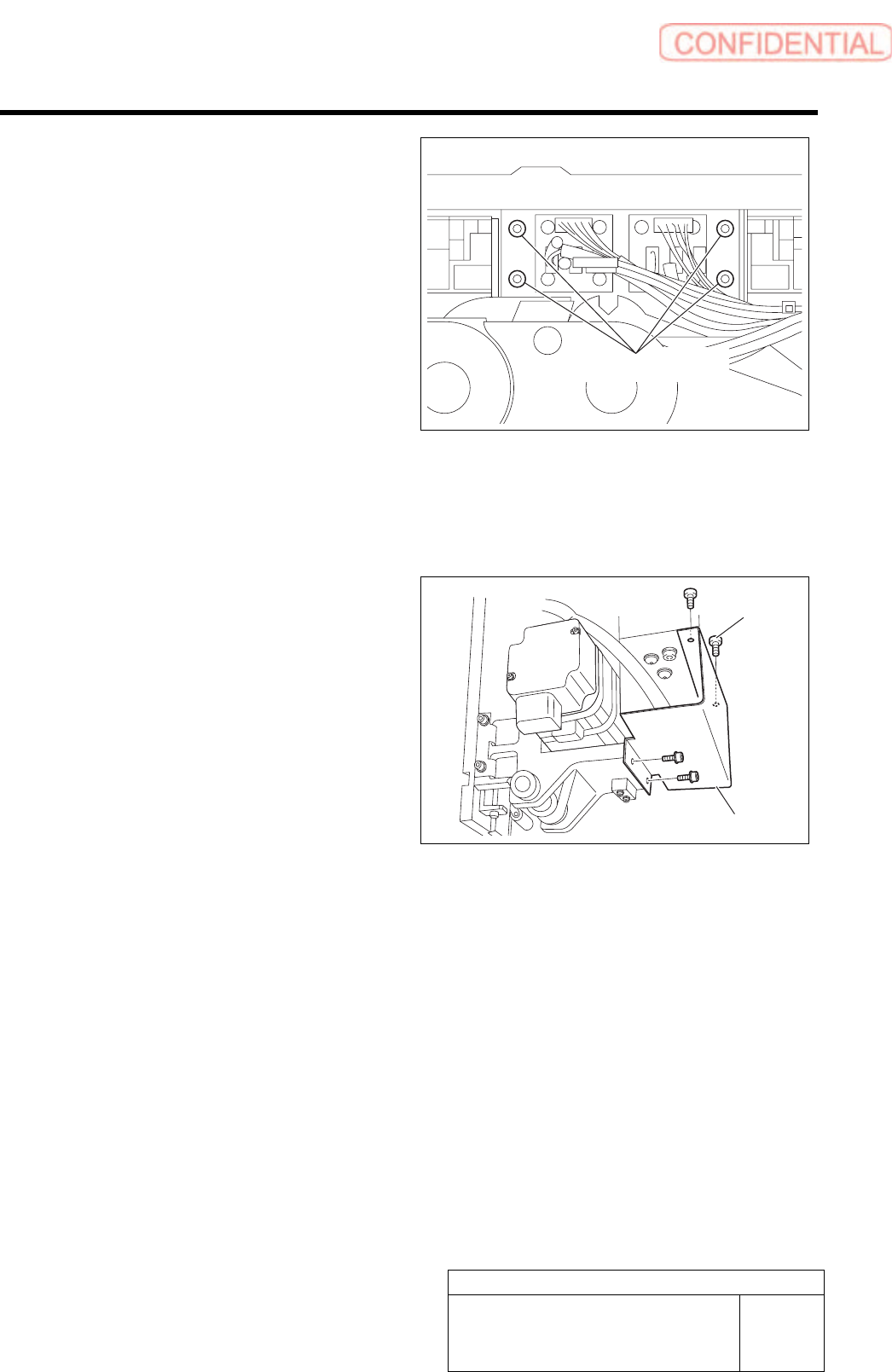
12 Fasten 4-C4x8 screws to install the bracket
that fastens the cable bear.
Lock Tight 242 is applied before installment.
13 Reconnect the disconnected sensor
connectors to the original positions.
Wire the connectors and fix them with Insulock.
14 Fasten 4-C3x6 screws to install the cover.
[Adjustment]
Conduct setup.
For setup procedure, refer to HLGB-10206 “F axis setup”.
4-C4x8
4-C3x6
Cover