MAN00000772_SI-G200BB_SVCPDFA.pdf - 第649页
Pickup Check Camera Part RPGB-10201-01 Pickup Check Camera Up/Down Cylinder Replacement SHEET 1/7 Pickup Check Camera Up/Down Cylinder Replacement [Removing the Cylinder] 1 Disconnect main air supply and po wer off. 2 Re…
F axis movable part
RPGB-10101-01
F Axis Belt Replacement Procedure
SHEET
9/9
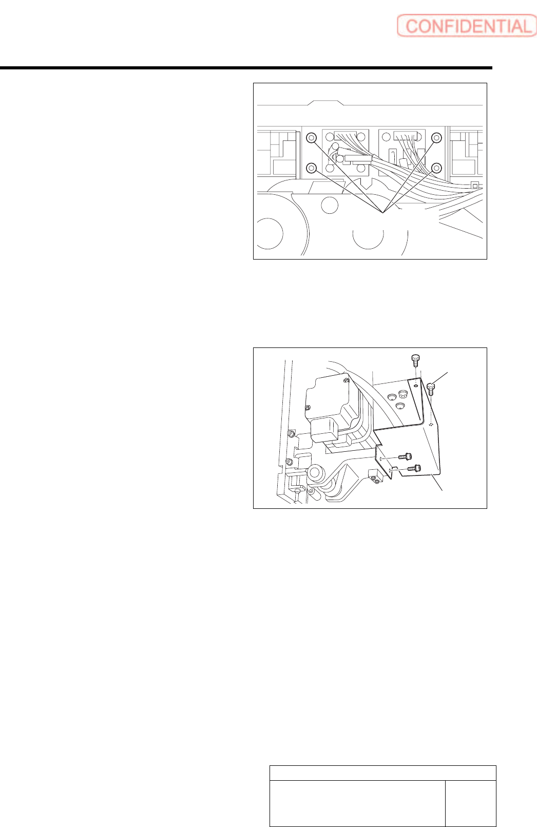
12 Fasten 4-C4x8 screws to install the bracket
that fastens the cable bear.
Lock Tight 242 is applied before installment.
13 Reconnect the disconnected sensor
connectors to the original positions.
Wire the connectors and fix them with Insulock.
14 Fasten 4-C3x6 screws to install the cover.
[Adjustment]
Conduct setup.
For setup procedure, refer to HLGB-10206 “F axis setup”.
4-C4x8
4-C3x6
Cover
Pickup Check Camera Part
RPGB-10201-01
Pickup Check Camera Up/Down
Cylinder Replacement
SHEET
1/7
Pickup Check Camera Up/Down Cylinder Replacement
[Removing the Cylinder]
1 Disconnect main air supply and power off.
2 Remove the F-axis unit.
For the F-axis unit removal procedure, refer to “F-Axis Belt Replacement Procedure [RPGB-10101-01]”.
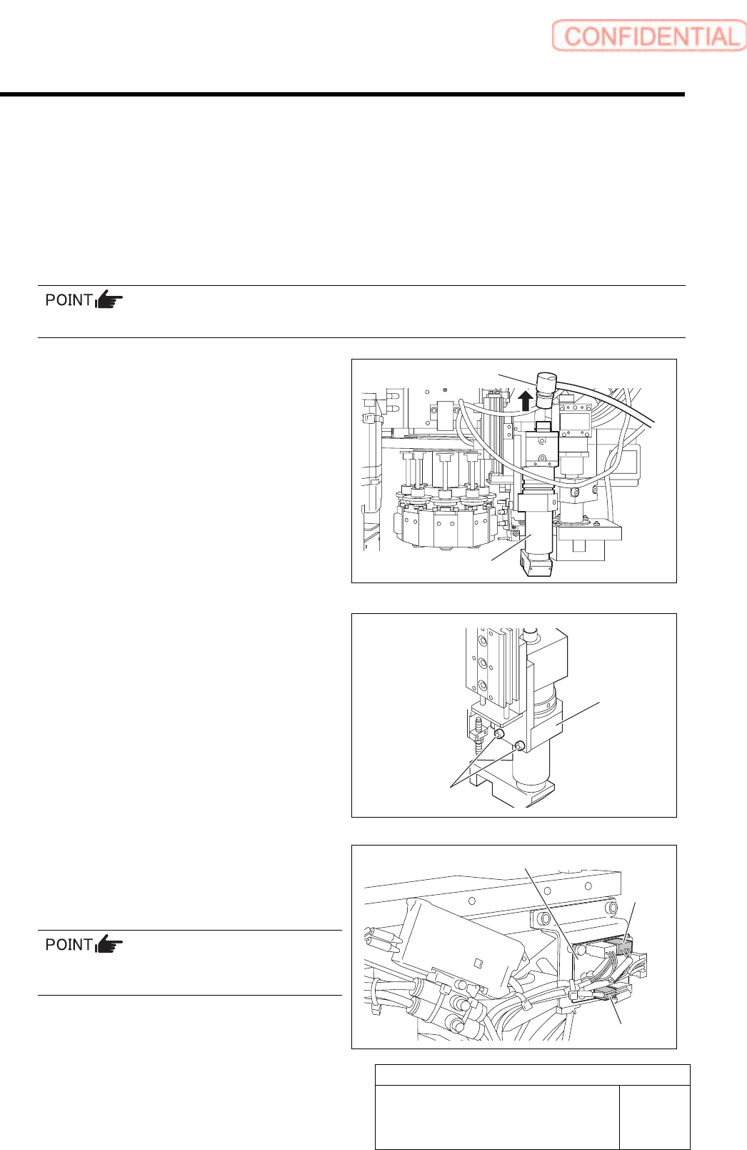
3 Remove the pickup check camera.
1. Disconnect connector CAM2-UF
(CAM2-UR) on the camera cable.
2. Loosen 2-CP4x8 to remove the pickup
check camera.
4 Disconnect two connector of SSB-2 and
SSB-4 from the SSB board on the side of
the head.
Remove the cable tie (Insulock) from SSB-2 and
SSB-4 cables as well.
CAM2-UF (CAM2-UR)
Pickup check camera
2-CP4x8
Pickup check
camera
SSB board
SSB-2
SSB-4
Pickup Check Camera Part
RPGB-10201-01
Pickup Check Camera Up/Down
Cylinder Replacement
SHEET
2/7
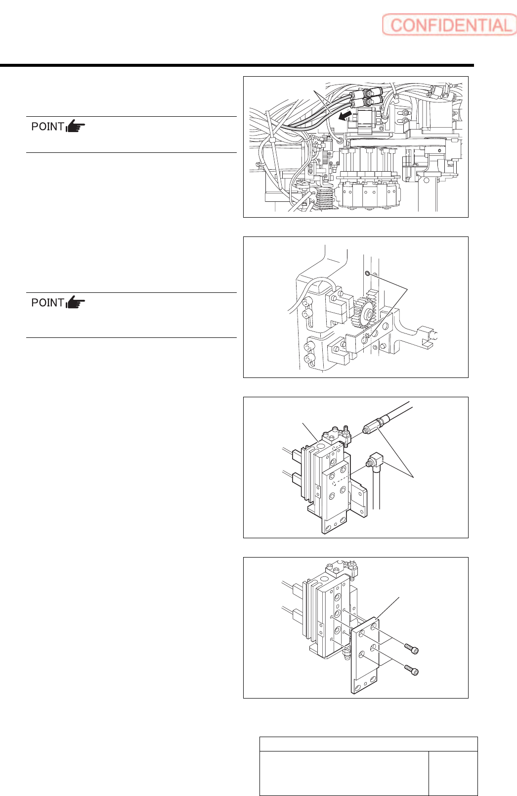
5 Disconnect the air tubes from the rear side
of the head.
Mark the tubes before disconnecting.
6 Loosen 2-CP4x6 to remove the pickup
check camera up/down unit from the rear
side of the head.
The attachment screw is located to the side of
the LM guide of the H-axis.
7 Disconnect the pipe fitting.
8 Loosen 4-CP3x6 to remove the camera
holder.
2-CP4x6
Air tubes
Pipe fitting
Pickup check camera
u
p
/down unit
Camera holder