MAN00000772_SI-G200BB_SVCPDFA.pdf - 第65页
SHEET Cassette specification is different from tray specification i n jig hole to be used. Holes on the front are for cassette specification and ho les on the ba ck are fo r tr ay spe c ificatio n with the o pt ical axis…

SHEET
2 Turn ON power for the unit to check that the
floodlighting area sensors are installed on
the right side of the unit.
3. Set the optical axis adjustment jig to the
position of supply No. 101.
1 ) Check that the replacing carrier has
been raised.
2 ) Set the optical axis adjustment jig on
the cassette table of supply No.101.
There should be no gap between the optical axis
adjustment jig and the cassette table.
4. Adjust mounting position of the area sensor
so that optical axis of the area sensor
passes through center of the hole on the
optical axis adjustment jig.
The right figure describes how to adjust the area
sensor on the right side as an example. Also adjust
position of the area sensor on the left side in the same
way.
1 ) Loosen the mounting bolts for the area
sensor to adjust up and downward
positions.
2 ) Loosen the cap screw on the lower side
of the bracket to adjust forward and
backward position of the area sensor.
Rear
Front
Optical axis
adjustment jig
Area sensor
Optical axis
25/73
WKGB-10104-03
Installing Tray Unit
(Including machine modification)
Install Tray Unit (Including machine modification)
.
SHEET
Cassette specification is different from tray
specification in jig hole to be used.
Holes on the front are for cassette specification
and holes on the back are for tray specification
with the optical axis adjustment jig being placed
on the cassette table.
5. When putting optical axis adjustment jig on
the supply No. 101, 120 and 140, check that
the sensor is turned ON.
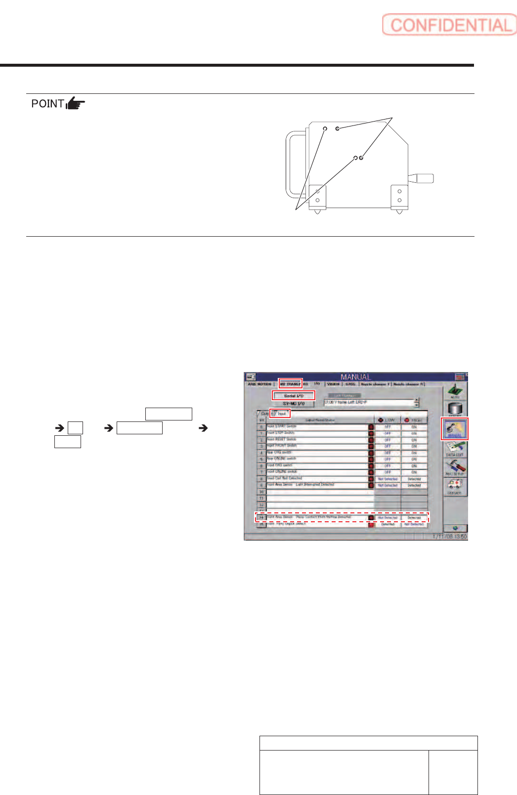
6. When shielding the area sensor by hand,
check that the sensor is turned OFF on the
I/O monitor screen.
1 ) Remove the optical axis adjustment
jig.
2 ) Click in an order of MANUAL menu
I/O tab Serial I/O button
Input tab.
Serial I/O screen is displayed.
3 ) When shielding the area sensor by
hand, check that the sensor is turned
OFF.
For tray specification
For cassette specification
Install Tray Unit (Including machine modification)
26/73
WKGB-10104-03
Installing Tray Unit
(Including machine modification)
Install Tray Unit (Including machine modification)
SHEET
27/73
WKGB-10104-03
Installing Tray Unit
(Including machine modification)
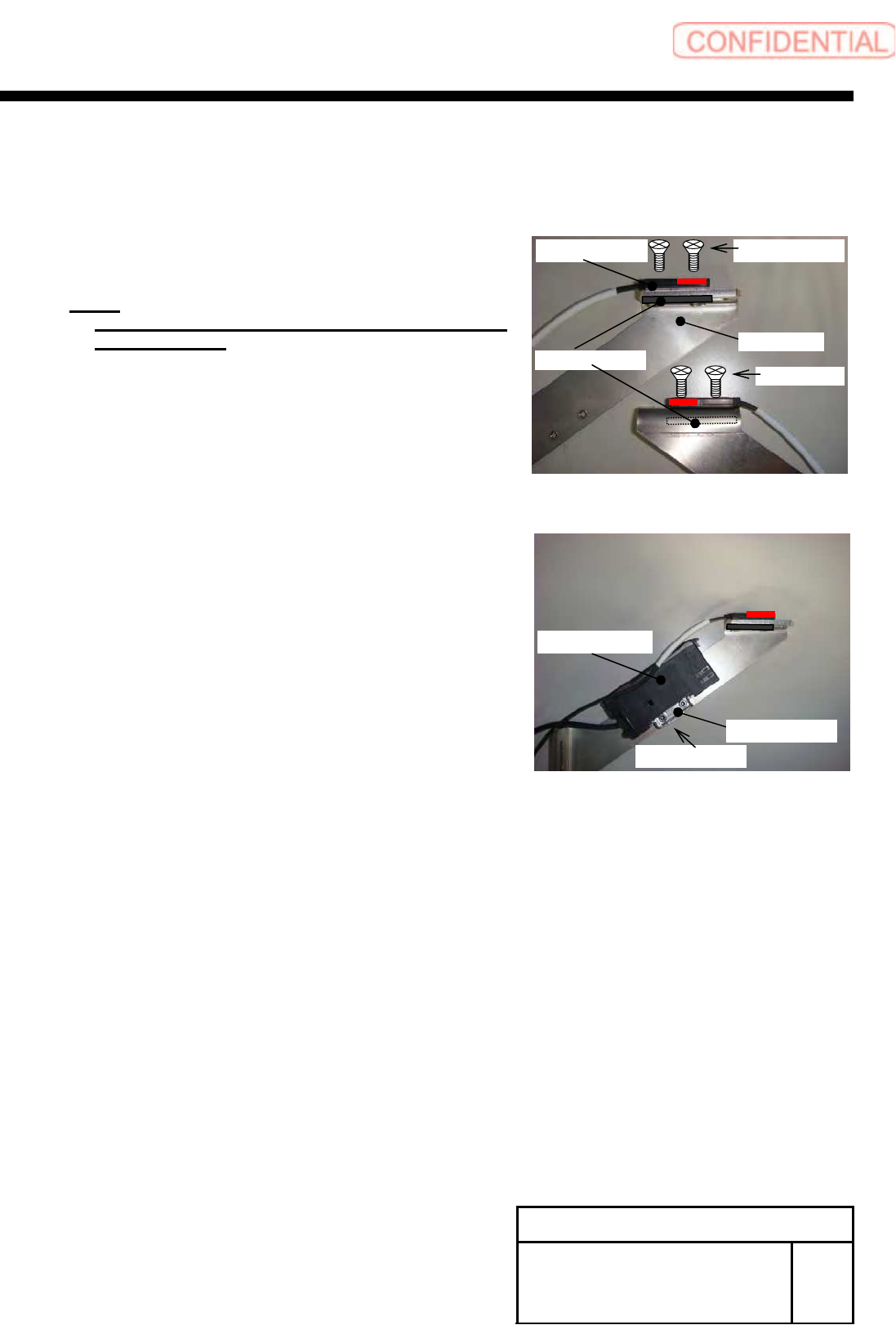
7 Install a cassette floating detection
sensor to the sensor bracket.
1. Install the sensor to the bracket with the 2-+K3x8
and plate nut.
NOTE:
Press the sensor against the sensor cable side and
temporarily fix it.
2. Install the bracket for fixing amplifier and sensor
amplifier to the sensor bracket on the right side.
2-CP3X5
Sensor amplifier
Bracket
Plate nut
2-+K3X8 Sensor
Bracket
2-+K3X8