MAN00000772_SI-G200BB_SVCPDFA.pdf - 第650页
Pickup Check Camera Part RPGB-10201-01 Pickup Check Camera Up/Down Cylinder Replacement SHEET 2/7 5 Disconnect the air tubes from the rear side of the head. Mark the tubes b efore disconnecting. 6 Loosen 2-CP4x6 to remov…
Pickup Check Camera Part
RPGB-10201-01
Pickup Check Camera Up/Down
Cylinder Replacement
SHEET
1/7
Pickup Check Camera Up/Down Cylinder Replacement
[Removing the Cylinder]
1 Disconnect main air supply and power off.
2 Remove the F-axis unit.
For the F-axis unit removal procedure, refer to “F-Axis Belt Replacement Procedure [RPGB-10101-01]”.
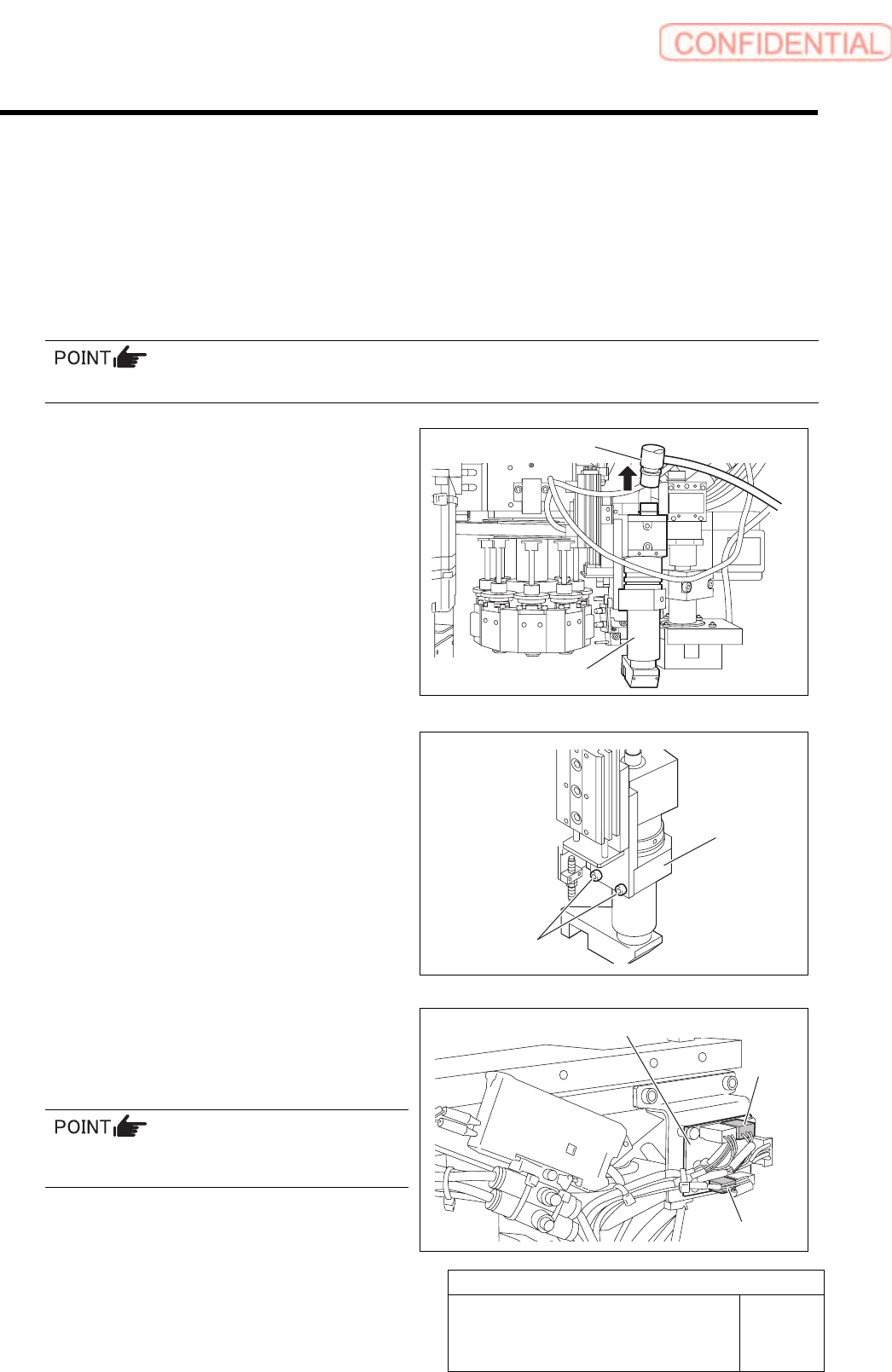
3 Remove the pickup check camera.
1. Disconnect connector CAM2-UF
(CAM2-UR) on the camera cable.
2. Loosen 2-CP4x8 to remove the pickup
check camera.
4 Disconnect two connector of SSB-2 and
SSB-4 from the SSB board on the side of
the head.
Remove the cable tie (Insulock) from SSB-2 and
SSB-4 cables as well.
CAM2-UF (CAM2-UR)
Pickup check camera
2-CP4x8
Pickup check
camera
SSB board
SSB-2
SSB-4
Pickup Check Camera Part
RPGB-10201-01
Pickup Check Camera Up/Down
Cylinder Replacement
SHEET
2/7
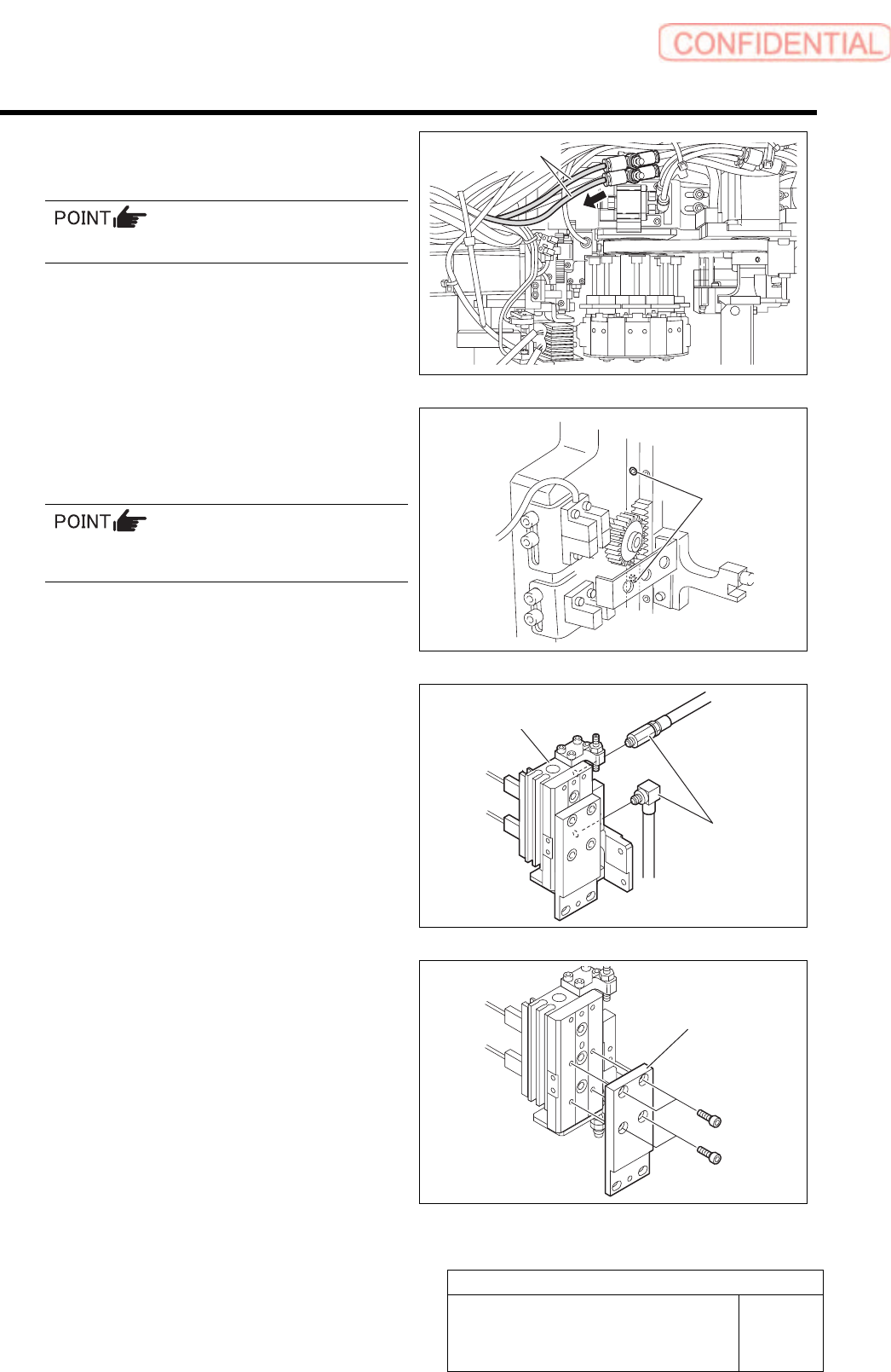
5 Disconnect the air tubes from the rear side
of the head.
Mark the tubes before disconnecting.
6 Loosen 2-CP4x6 to remove the pickup
check camera up/down unit from the rear
side of the head.
The attachment screw is located to the side of
the LM guide of the H-axis.
7 Disconnect the pipe fitting.
8 Loosen 4-CP3x6 to remove the camera
holder.
2-CP4x6
Air tubes
Pipe fitting
Pickup check camera
u
p
/down unit
Camera holder
Pickup Check Camera Part
RPGB-10201-01
Pickup Check Camera Up/Down
Cylinder Replacement
SHEET
3/7
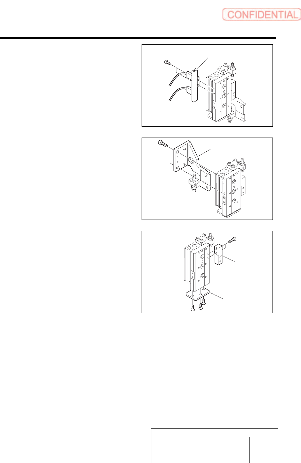
9 Loosen 2-CP3x5 to remove the cylinder
sensor holder.
10 Loosen 2-CP4x8 to remove the main
bracket.
11 Loosen 2-CP2x6 to remove the downward
end stopper block.
12 Loosen 3-+K3x6 to remove the cylinder
cover.
Cylinder sensor holder
Main bracket
Stopper block
Cylinder cover