MAN00000772_SI-G200BB_SVCPDFA.pdf - 第655页
Pickup Check Camera Part RPGB-10201-01 Pickup Check Camera Up/Down Cylinder Replacement SHEET 7/7 15 Move the cylinder up and downward to adjust the installing positio n of the cylinder up/down sensor . 1. Click the Chec…
Pickup Check Camera Part
RPGB-10201-01
Pickup Check Camera Up/Down
Cylinder Replacement
SHEET
6/7
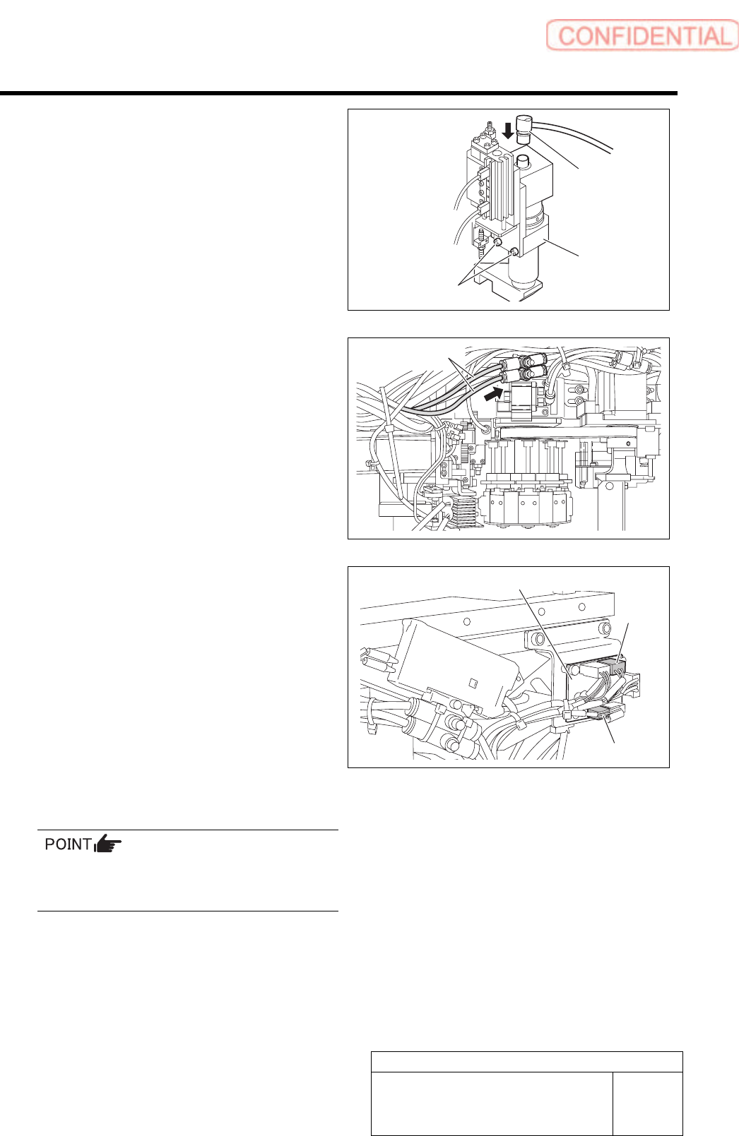
10 Secure the pickup check camera with
2-CP4x8 and connect the CAM2-UF camera
cable connector.
11 Connect the air tubes to the speed controller
on the rear side of the head. After
connecting the air tubes, bundle them
together using the cable tie (Insulock).
12 Connect SSD-2 and SSB-4 to the SSB
board on the side of the head, and then
fasten the cables with the cable tie
(Insulock).
13 Install the F-axis to the head.
For the F-axis unit removal procedure, refer to
“F-Axis Belt Replacement Procedure
[RPGB-10101-01]”.
14 Connect the air and turn on the system
power.
CAM2-UF
Pickup check
camera
Air tubes
SSB board
SSB-2
SSB-4
2-CP4x8
Pickup Check Camera Part
RPGB-10201-01
Pickup Check Camera Up/Down
Cylinder Replacement
SHEET
7/7
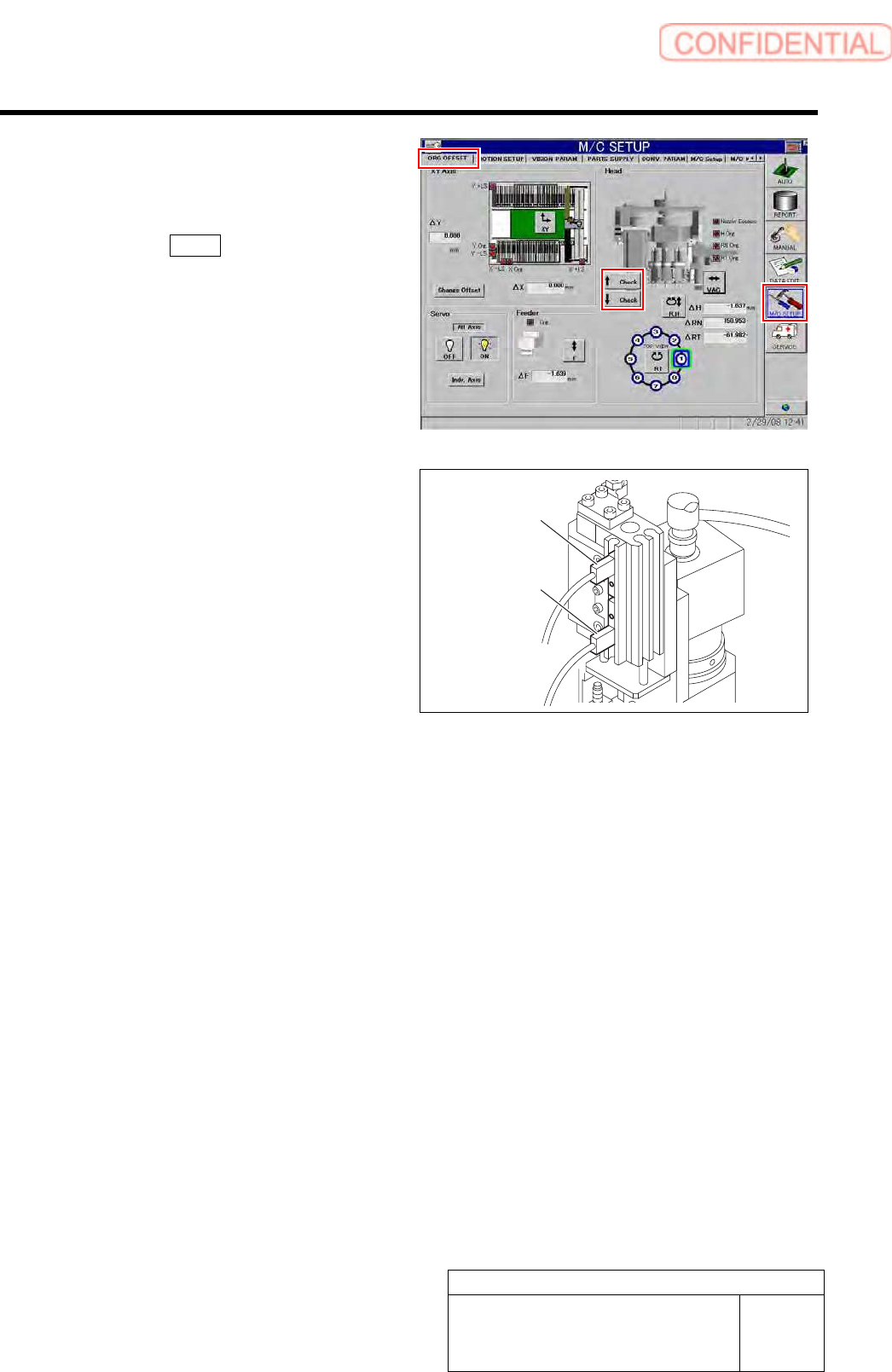
15 Move the cylinder up and downward to
adjust the installing position of the cylinder
up/down sensor.
1. Click the Check button on the ORG
OFFSET screen of the M/C SETUP.
2. Adjust the sensor position so that LED
on the sensor lights up at positions of
cylinder rising end and lowering end.
16 Execute pickup camera set up and pickup check camera calibration.
・ For the pickup check camera setup procedure, refer to “Pickup Check Camera Setup [HLGB-10208-01]”.
・ For the pickup check camera calibration procedure, refer to “Pickup Check Camera Calibration [HLGB-10308-01]”.
Cylinder up senso
r
Cylinder down
senso
r
Pickup Check Camera Part
RPGB-10202-01
Pickup Check Light Up/Down
Cylinder Replacement
SHEET
1/7
Pickup Check Light Up/Down Cylinder Replacement
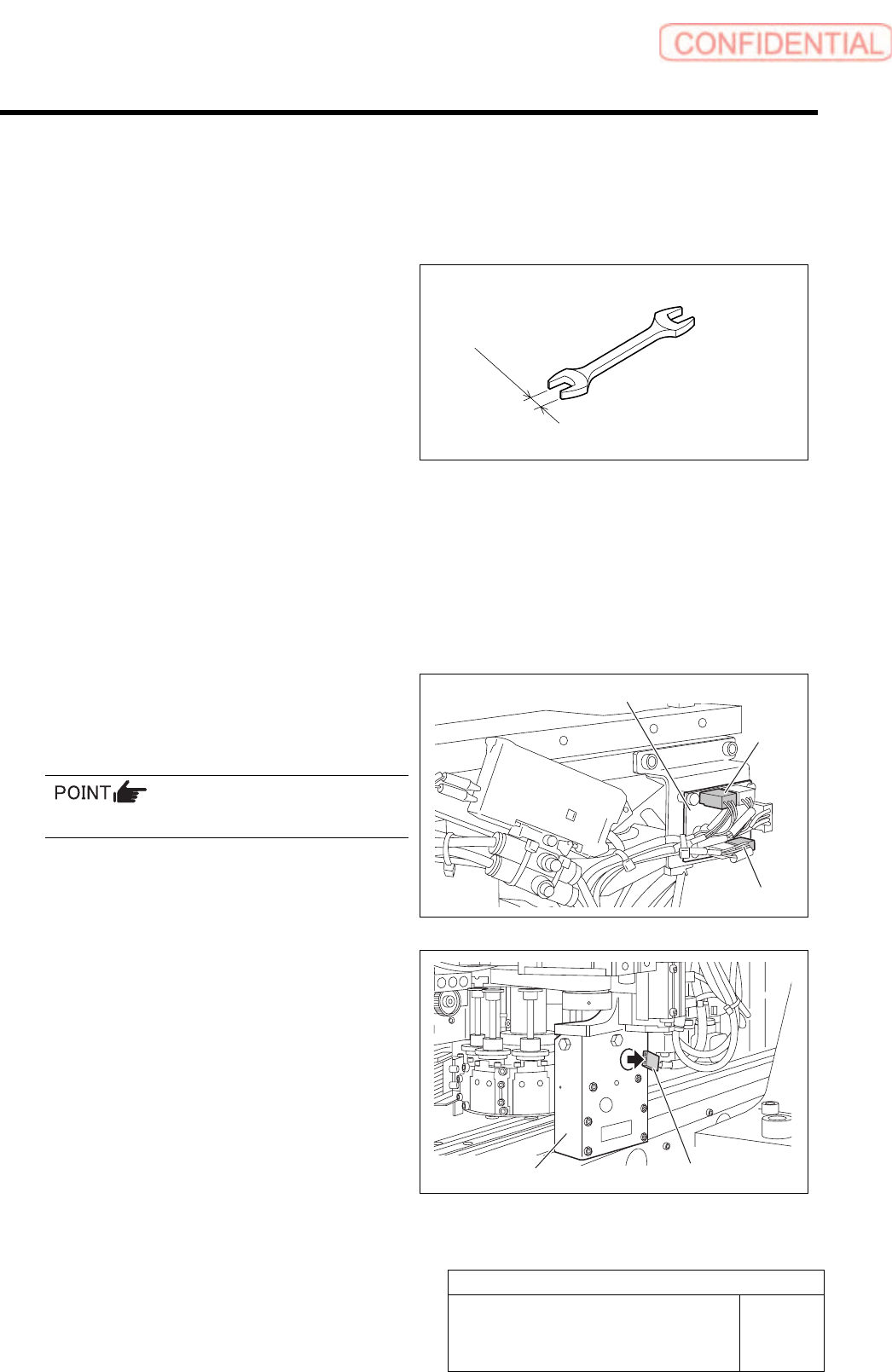
[Necessary jigs]
• Spanner (width across flats: 3 [mm])
3.0 mm
[Removing the Cylinder]
1 Move the head to a better position to work
with, and then turn off the power of the
mounter.
2 Disconnect air supply of mounter.
3 Disconnect the connector of SSB-3 and
SSB-5 from the SSB board on the side of
the head.
Remove the cable tie (Insulock) from the cables.
4 Disconnect the connector of LEDF2
(LEDR2) from the LED light unit.
5 To prevent the light unit from falling off,
fasten the light unit to the motor bracket
using the cable tie (Insulock).
SSB board
SSB-3
SSB-5
LEDF2 (LEDR2)
Light unit