MAN00000772_SI-G200BB_SVCPDFA.pdf - 第661页
Pickup Check Camera Part RPGB-10202-01 Pickup Check Light Up/Do wn Cylinder Replacement SHEET 6/7 8 Connect the SSB-3 and SSB-5 connectors to the SSB board. 9 Bundle the cable and air tube togeth er using the cable tie (…
Pickup Check Camera Part
RPGB-10202-01
Pickup Check Light Up/Down
Cylinder Replacement
SHEET
5/7
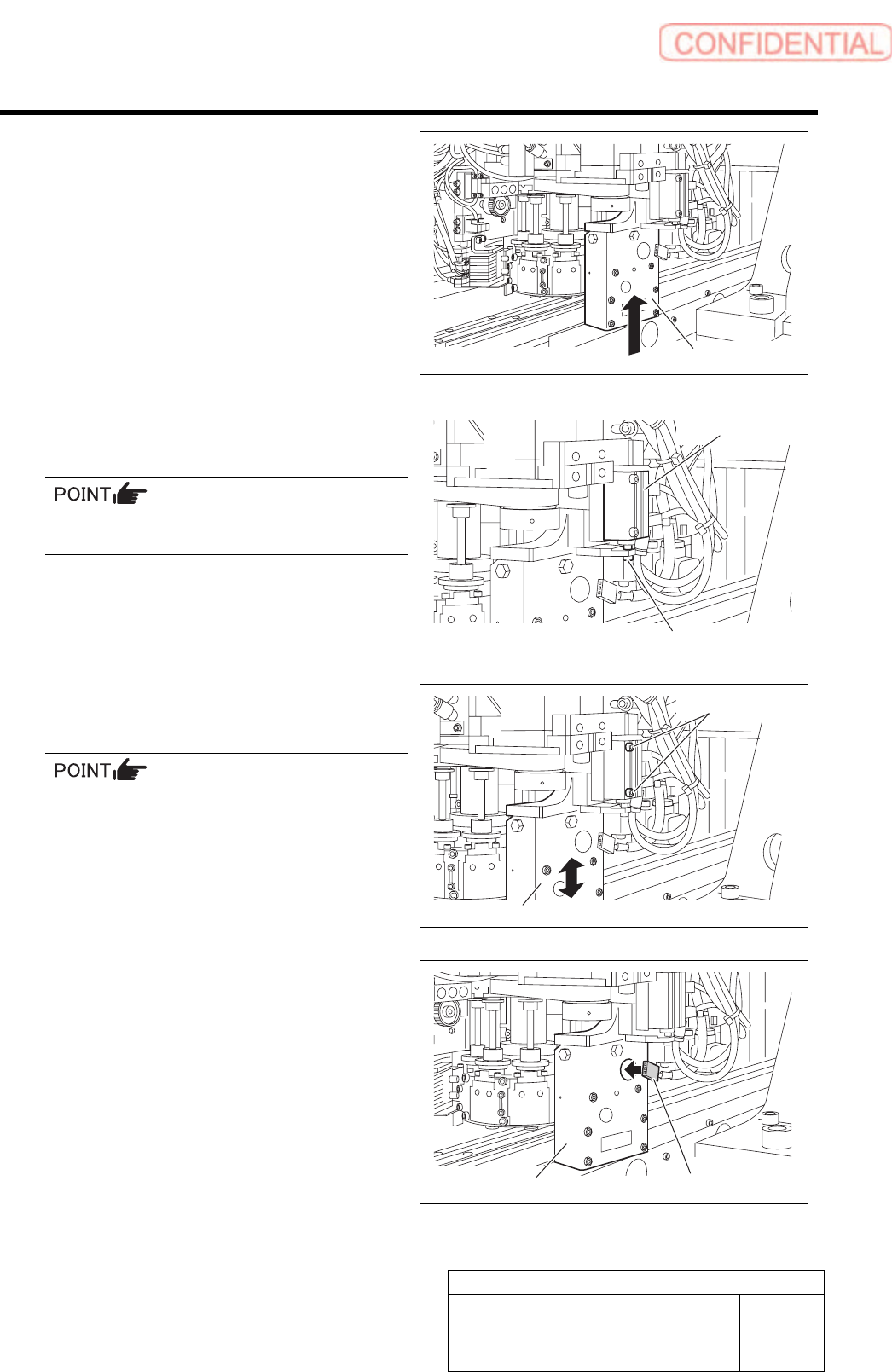
4 Attach the slide block to the linear rail
together with the light unit.
5 Join the rod end and the cylinder joint with
the collar and CP2x6.
Apply small amount of LOCKTITE 242 to
CP2x6.
6 While moving the light up/down with your
hand, fix 2-CP2.5x22 screw little by little.
After securing the cylinder, make sure the light
unit descends smoothly by its own weight.
7 Connect the connector of LEDF2 (LEDR2)
to the light unit.
Light unit
CP2x6
Cylinder
Light unit
CP2.5x22
Light unit
LEDF2 (LEDR2)
Pickup Check Camera Part
RPGB-10202-01
Pickup Check Light Up/Down
Cylinder Replacement
SHEET
6/7
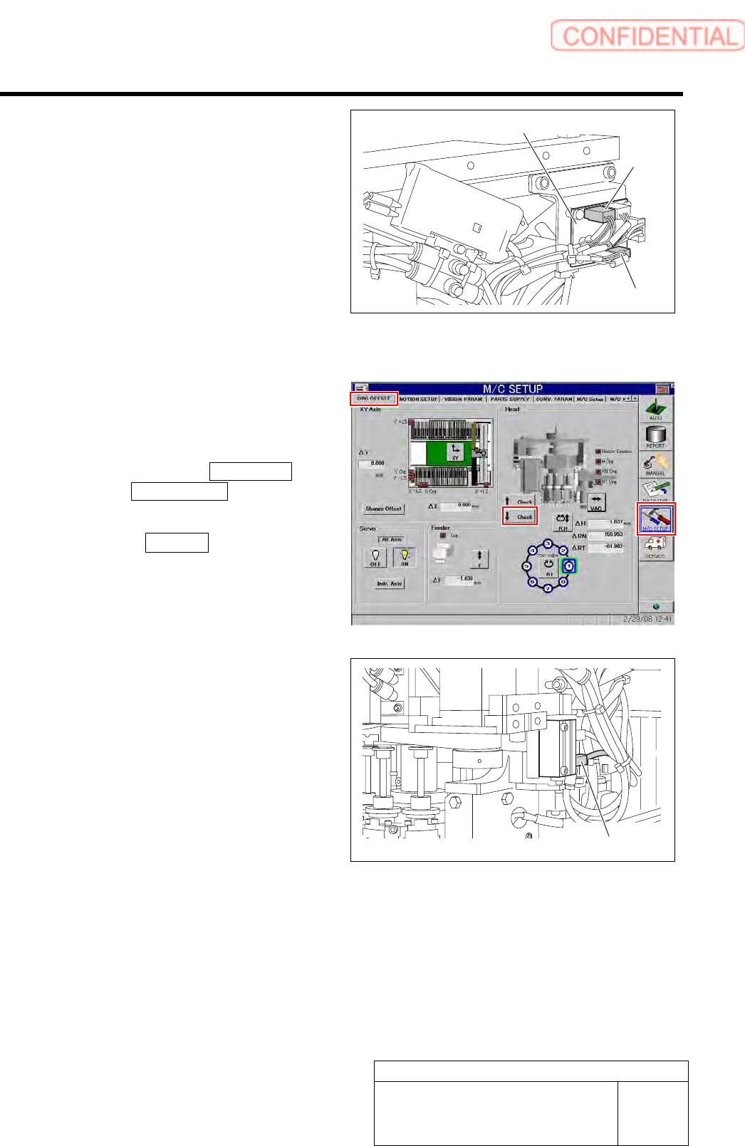
8 Connect the SSB-3 and SSB-5 connectors
to the SSB board.
9 Bundle the cable and air tube together using
the cable tie (Insulock).
10 Connect the air supply and power on.
11 Adjust and check the position of the cylinder
up/down sensor using the buttons on the
ORG offset screen of M/C SETUP.
1. Click in an order of M/C SETUP
menuORG OFFSET tab.
The origin offset careen is displayed.
2. Click the ↓ Check button to check a
position of the lowering end of the
light unit.
3. Adjust the position of the lower
cylinder sensor and adjust the position
of the lowering end of the light unit.
SSB board
SSB-3
SSB-5
Cylinder sensor
Pickup Check Camera Part
RPGB-10202-01
Pickup Check Light Up/Down
Cylinder Replacement
SHEET
7/7
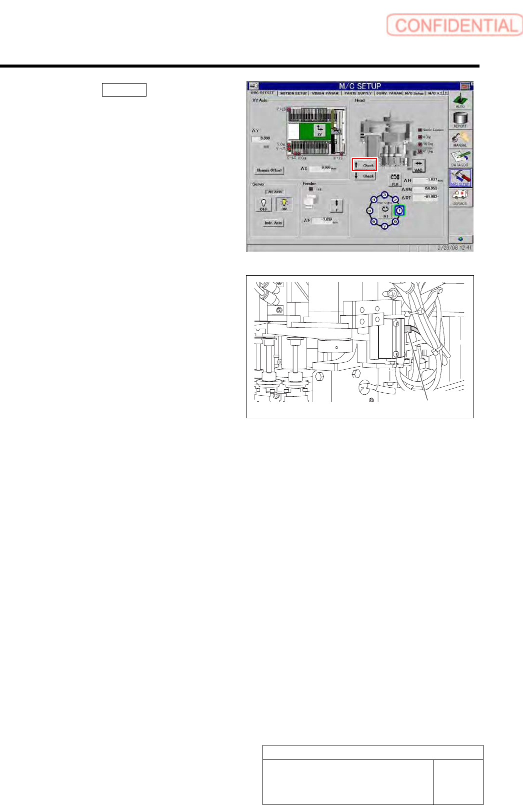
4. Click the ↑ Check button to check a
position of the rising end of the light
unit.
5. Adjust the position of the upper
cylinder sensor and adjust the position
of the rising end of the light unit.
Cylinder sensor