MAN00000772_SI-G200BB_SVCPDFA.pdf - 第663页
Ch ange Procedu re fo r Head U n i t Change proc edure for Head Unit [Necess a r y jigs] He ad block Assembly plate(G200 o riginal) [Disassembly] 1 Expand conveyo r w idth to th e m axi m um. 2 T u rn of f a powe r s up …
Pickup Check Camera Part
RPGB-10202-01
Pickup Check Light Up/Down
Cylinder Replacement
SHEET
7/7
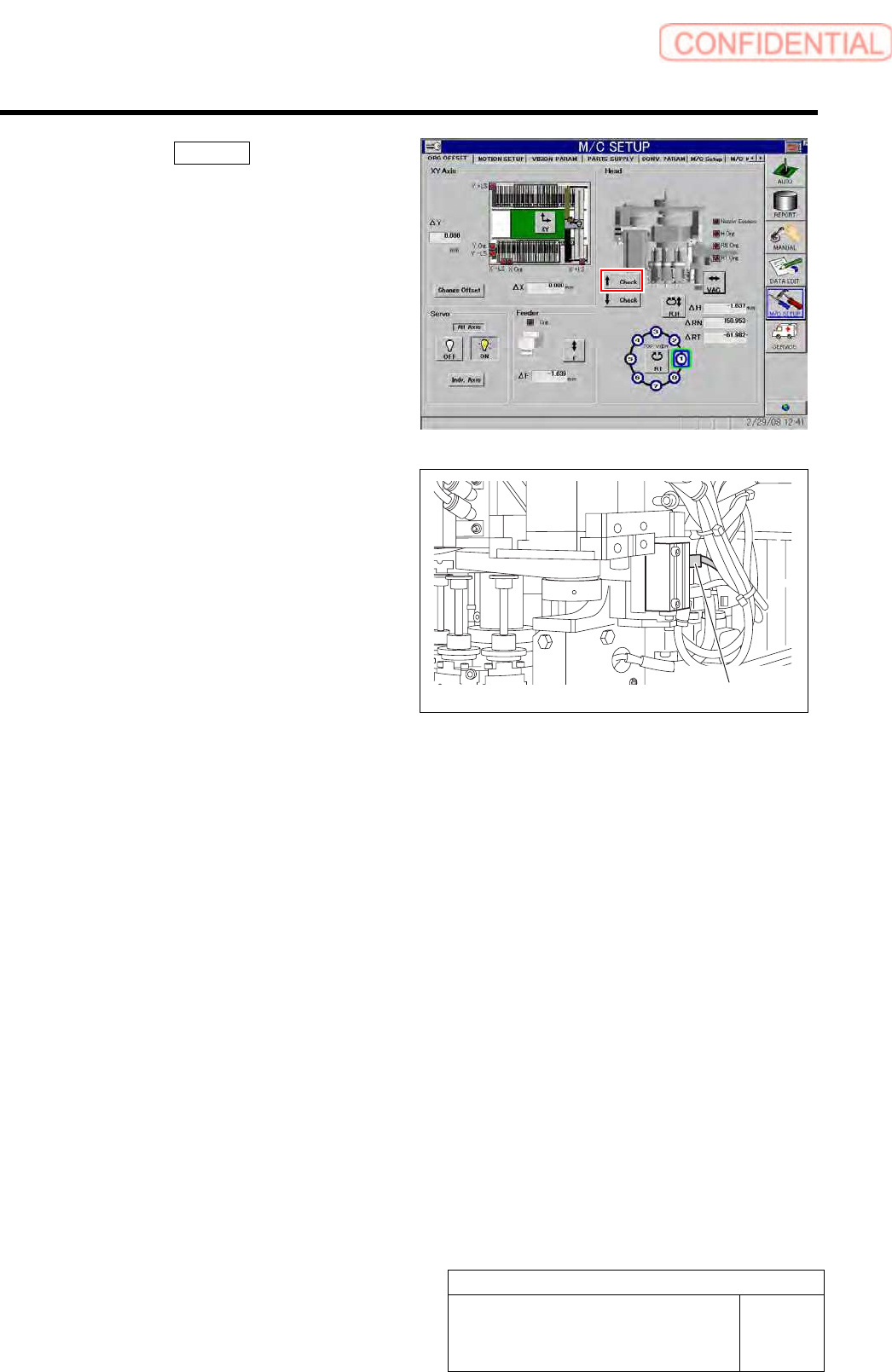
4. Click the ↑ Check button to check a
position of the rising end of the light
unit.
5. Adjust the position of the upper
cylinder sensor and adjust the position
of the rising end of the light unit.
Cylinder sensor
Change Procedure for Head Unit
Change procedure for Head Unit
[Necessary jigs]
Head block
Assembly plate(G200 original)
[Disassembly]
1 Expand conveyor width to the maximum.
2 Turn off a power supply and close an air main
cock.
3 Open the front and rear side doors of the main
body.
4 Push the X-axis frame to the center and the head base
to an easy-to-work position.
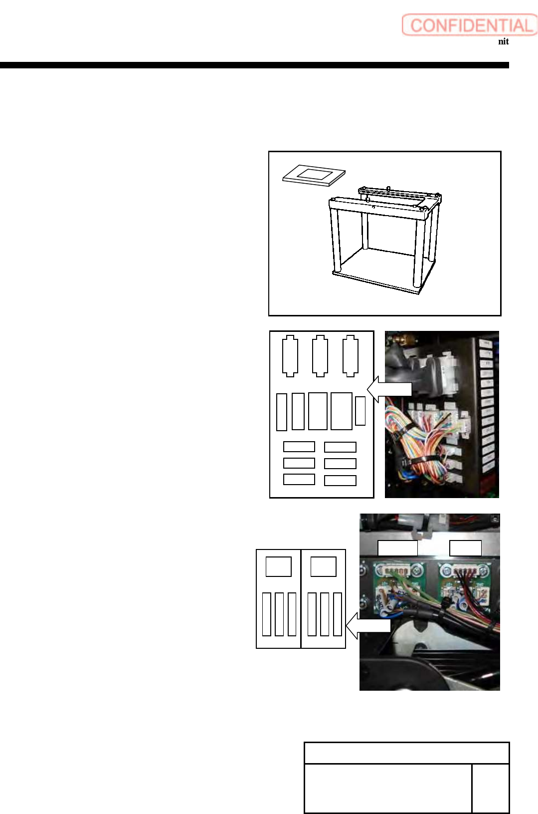
5 Remove all nozzles.
6
Remove all the following connectors ,
and cut the cable tie locking the wiring.
1. PWB camera (CAME1)
2. Connector plate
(HM,RTM,RNM,CSFT,FSEN2,LED,PD,CSFT-LS,HE,
RTE,RNE,VAC-2,RTS,RNS)
3. Pick up Camera(CAME2)
4. HLSB and PD-LSB
(BS-NZL,PDLS-3,PDLS-4,HLS-2,HLS-3,HLS-4)
5. Encoder (DE1)
Change Procedure for Head
Unit
RPGB-10301-1
SEET
1/4
CSFT
FSEN2
LED
PD
CSFT-LS
HM
RTM
RNM
HE VAC-2
RTS
RNE
RTE
Layout
RNS
HLSB
PD-LSB
Layout
BS
-
NZL
PDLS
-
3
PDLS
-
4
HLS
-
2
HLS
-
3
HLS
-
4
Change Procedure for Head Unit
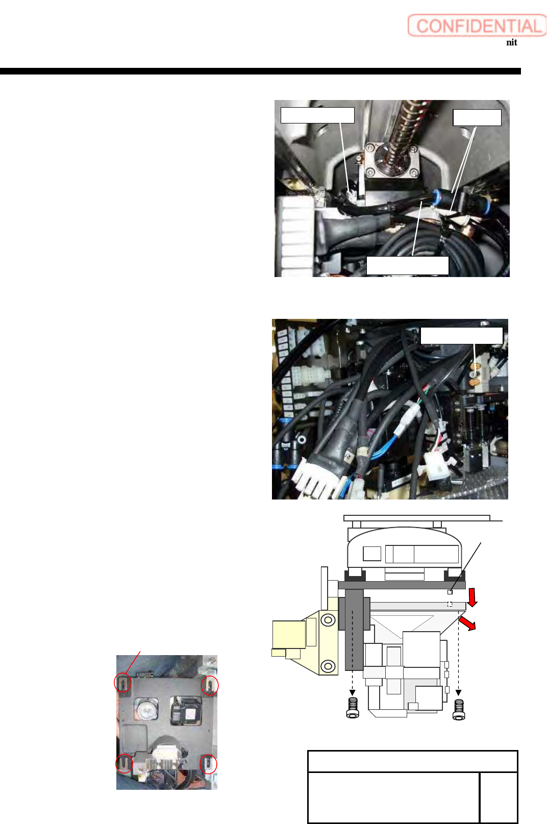
7 Pull out the air tubes (D6 and D8)(2pcs) from the Joint.
Attention
Mark it before pulling out a tube.
8 Pull out the air tube (D6 )from the Valve.
Attention
Mark it before pulling out a tube.
9 Remove the screws 4-C6x20,and pull out the head
unit from the parallel pin.
Attention
As the head unit is heavy, carefully hold the
head unit while working.
Move the head unit in the direction of the arrow
and remove.
Be careful to the lose of the spacer.
Change Procedure for Head
Unit
RPGB-10301-1
SEET
2/4
Valve
manifold
air tubes
Joint
Parallel pin
C6x20
Spacer