MAN00000772_SI-G200BB_SVCPDFA.pdf - 第673页
Ch ange Procedu re for RT Axi s Moto r U n i t 6 Remov e the screws (4-C5x 12) and moto r br acket. 7 Remov e the screws (2-H 2.5x 4, 2-H 3x5) , set shoe (2) and pulley . CAUTION There i s a set sho e beh i n d th e scre…
Change Procedure for RT Axis Motor Unit
Change Procedure for RT Axis Motor Unit
[Necessary Jigs]
Tension Meter(UNITTA U-507)
Belt Tension JIG (B)
[Disassembly]
1 Open the front and rear slide doors of the main body.
2
Push the head base to the center.
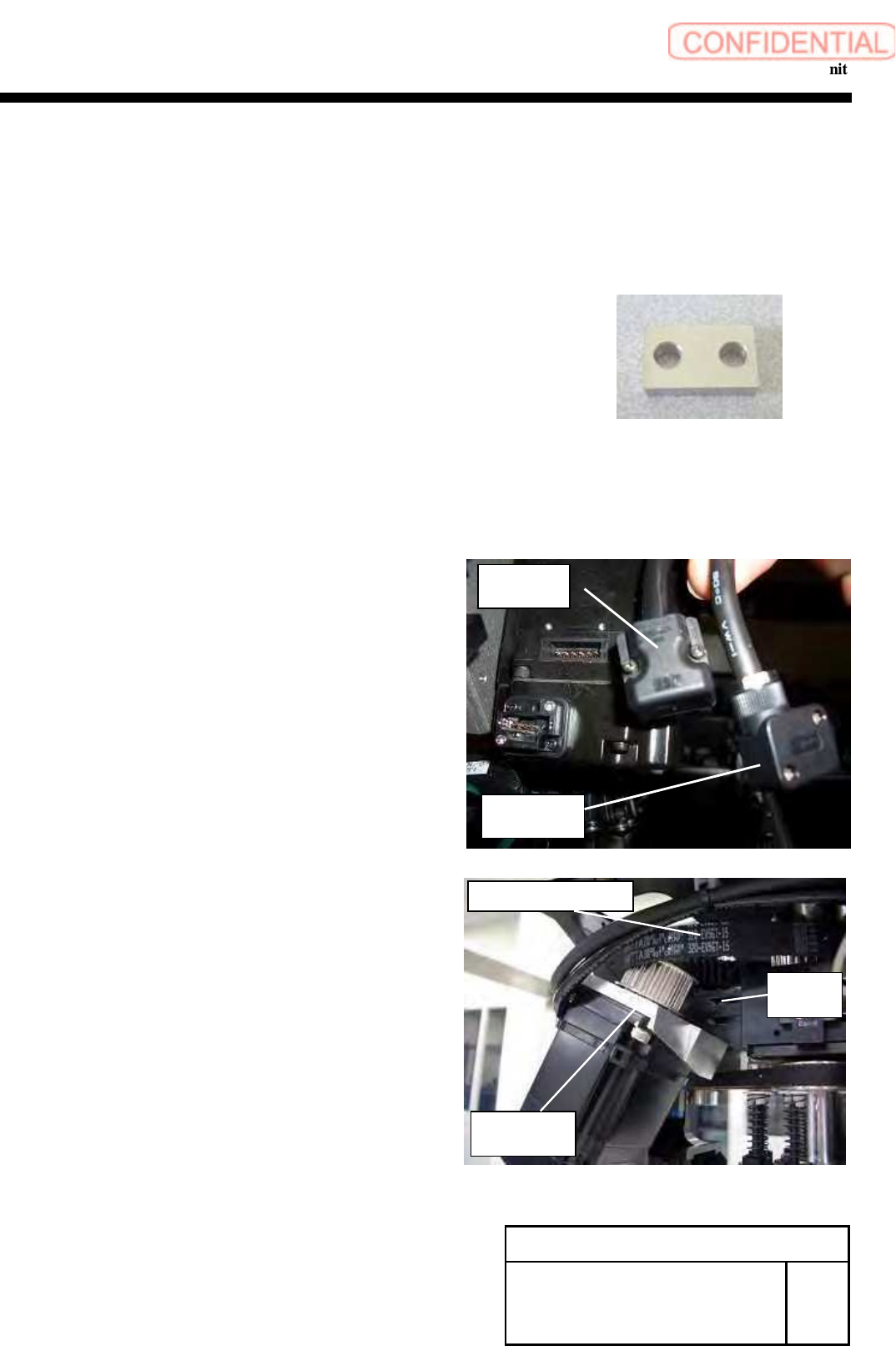
3 Cut the cable tie locking the wiring of the motor.
4 Remove the power cable and the encoder cable.
5 Remove the screws (4-C4x18), and detach
the bracket.
Change Procedure for RT-axis
Motor
Unit
RPGB-10601-1
SEET
1/4
Encoder
cable
Power
cable
RT Axis Motor
Bracket
C
4
x
18
W4
RT Axis Timing Belt
Change Procedure for RT Axis Motor Unit
6 Remove the screws (4-C5x12) and motor bracket.
7
Remove the screws (2-H2.5x4, 2-H3x5), set shoe (2)
and pulley.
CAUTION
There is a set shoe behind the screw which
locks the pulley in the keyless position.
Remove the set shoe, and safekeep it not to lose it.
Motor Bracket
Pulley
C5x12
H3
x
5
Set Shoe
H2.5x4
Key
Change Procedure for RT-axis
Motor Unit
RPGB-10601-1
SEET
2/4
Change Procedure for RT Axis Motor Unit
[Reassembly]
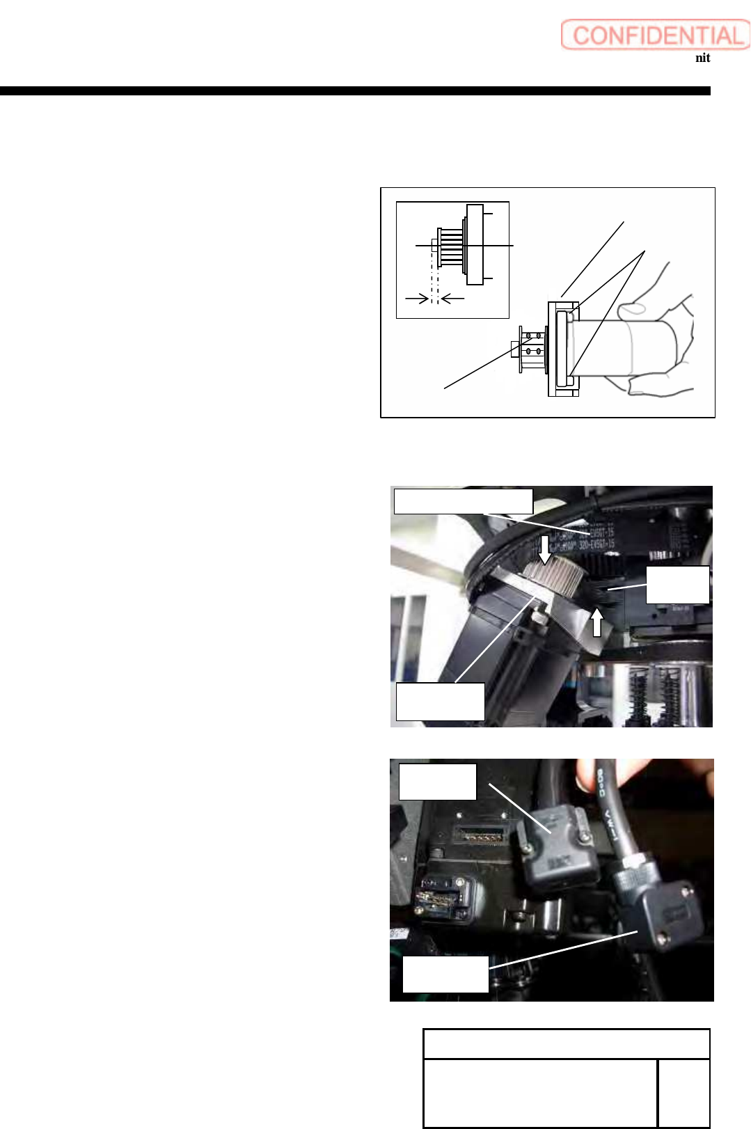
8 Attach the pulley
1. Insert the key into the shaft of a new motor.
CAUTION
Smoothly insert the key without stress to
the shaft of motor.
2. Insert the pulley into the shaft of the motor.
3. Put the set shoe deep into the hole of the screws (2-H3x5),
which is to lock the pulley in the keyless position.
4. Apply adhesive (Locktite 242) to the screws (2-H2.5x4)
and (2-H3x5).
5. Refer to the figure, 2.5mm of the gap between shaft and
pully then tighten the screws (2-H2.5x4, 2-H3x5).
6. Apply adhesive (Locktite 242) to the screws (4-C5x12),
and apply the bracket to the motor.
9 Install the motor bracket to the head housing.
1. Apply the RT-axis timing belt to the pulley on the motor side.
2.Lock the bracket to the head housing by
temporarily fastening screws (4-C4x18, W4).
10 Connect the power cable and the encoder cable
to the motor.
Change Procedure for RT-axis
Motor Unit
RPGB-10601-1
SEET
3/4
Encoder
Cable
Power
Cable
H3
x
5
Set Shoe
H2.5x4
Motor Bracket
C5x12
2.5mm
RT axis motor
bracket
C
4
x
18
W4
RT axis timing belt