MAN00000772_SI-G200BB_SVCPDFA.pdf - 第675页
Ch ange Procedu re fo r RT-axis Moto r Unit 11 Mov e the brac ket t o the position in whic h the tensio n of R T -axis timing bel t gains by adjustme nt scre w . Measure the tensio n with T e nsion Mete r, and loc k the …
Change Procedure for RT Axis Motor Unit
[Reassembly]
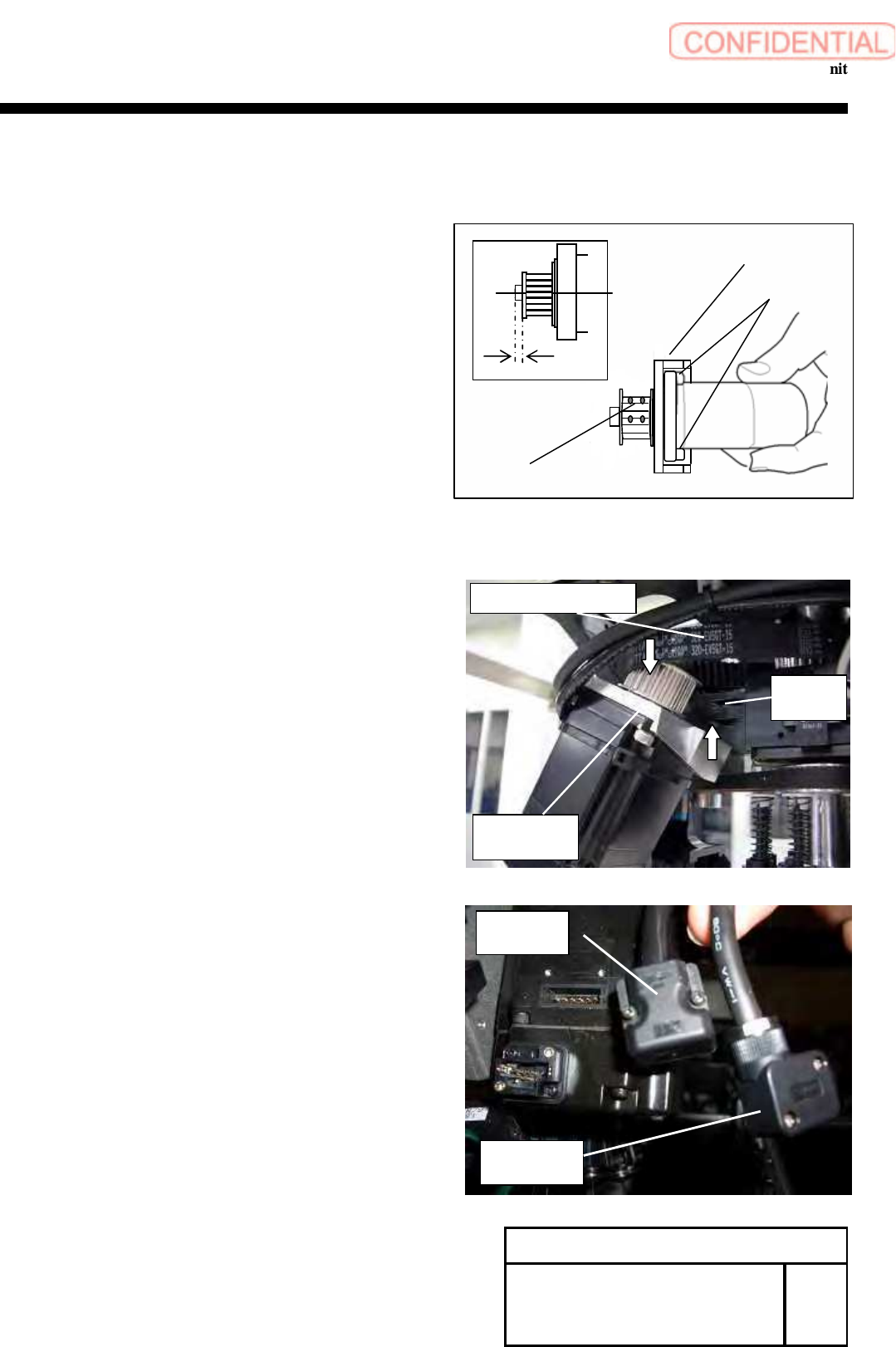
8 Attach the pulley
1. Insert the key into the shaft of a new motor.
CAUTION
Smoothly insert the key without stress to
the shaft of motor.
2. Insert the pulley into the shaft of the motor.
3. Put the set shoe deep into the hole of the screws (2-H3x5),
which is to lock the pulley in the keyless position.
4. Apply adhesive (Locktite 242) to the screws (2-H2.5x4)
and (2-H3x5).
5. Refer to the figure, 2.5mm of the gap between shaft and
pully then tighten the screws (2-H2.5x4, 2-H3x5).
6. Apply adhesive (Locktite 242) to the screws (4-C5x12),
and apply the bracket to the motor.
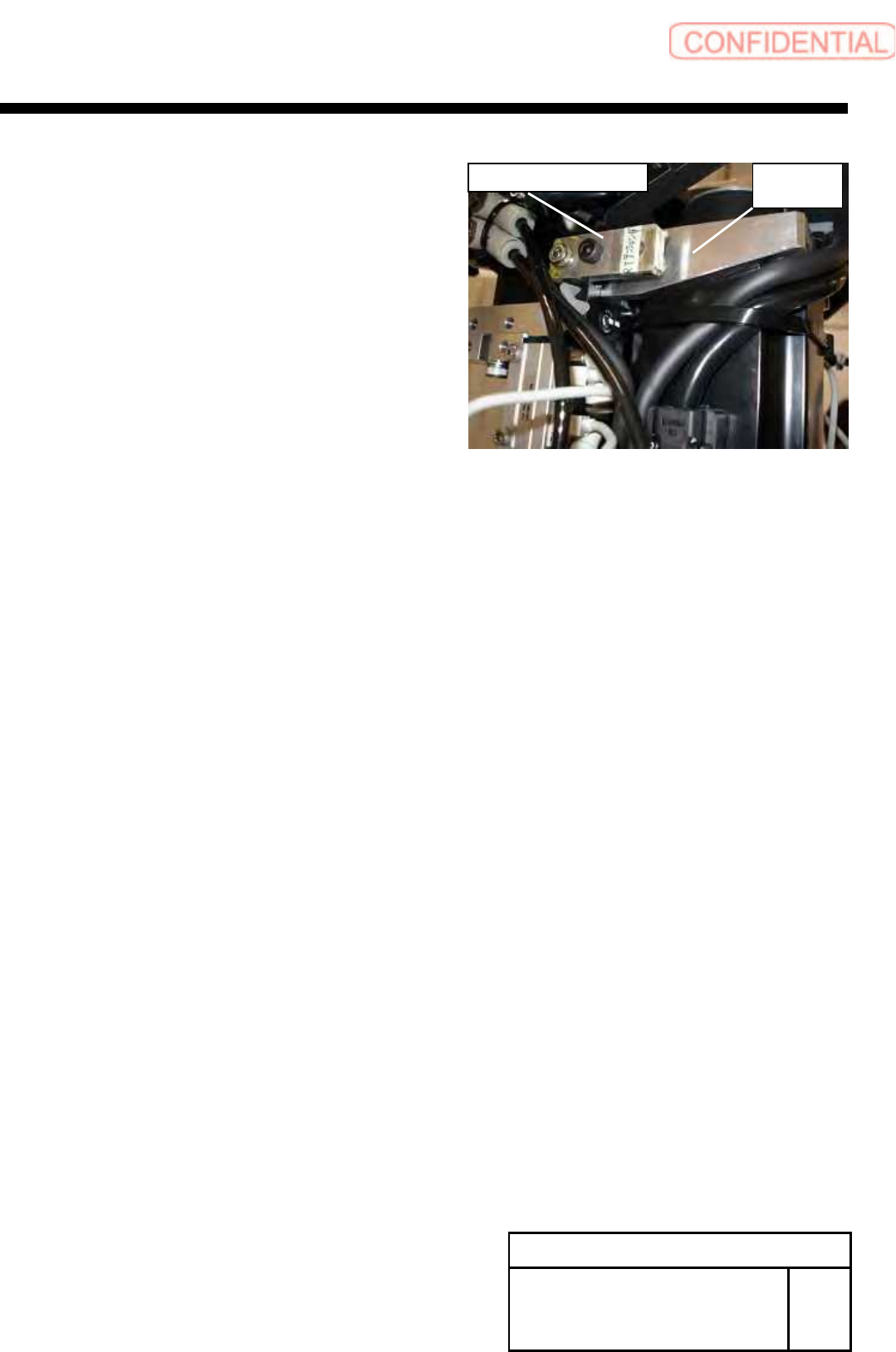
9 Install the motor bracket to the head housing.
1. Apply the RT-axis timing belt to the pulley on the motor side.
2.Lock the bracket to the head housing by
temporarily fastening screws (4-C4x18, W4).
10 Connect the power cable and the encoder cable
to the motor.
Change Procedure for RT-axis
Motor Unit
RPGB-10601-1
SEET
3/4
Encoder
Cable
Power
Cable
H3
x
5
Set Shoe
H2.5x4
Motor Bracket
C5x12
2.5mm
RT axis motor
bracket
C
4
x
18
W4
RT axis timing belt
Change Procedure for RT-axis Motor Unit
11 Move the bracket to the position in which the tension of
RT-axis timing belt gains by adjustment screw. Measure the
tension with Tension Meter, and lock the bracket in the
position in which the tension becomes 96±5N.
(4 point measure)
UNITTA
U-507
Weight 4.0gf/m
Width 15mm
Span 95mm
12 Detach the Belt Tension JIG when the adjustment ends.
[Adjustment]
The exchange only of motors need not do the
“setup” and “calibration”.
Change Procedure for RT-axis
Motor Unit
RPGB-10601-1
SEET
4/4
Motor
Bracket
Belt Tension JIG
Change Procedure for Rotary Encoder
Change Procedure for Rotary Encoder
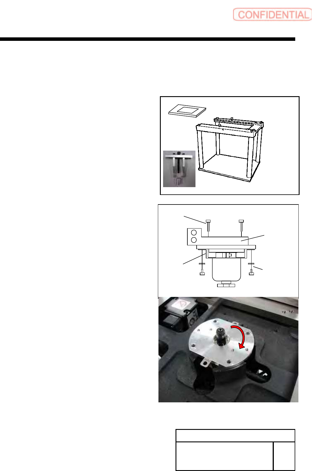
[Necessary Jigs]
Head Block
Assembly Plate (For G200)
Bearing remove JIG
[Disassembly]
1 For the removal procedure for the head unit.
Refer to RPGB-10301-1.
2 Remove the screws (2-CP3x4,2-W3).
3 Remove the screws (2-B3x16) and manifold.
4 Remove the encoder bearing holder.
1. Remove the screws (4-C3x8).
2. Rotate the encoder bearing holder to the
position of figure.
W3
CP3x4
Leaf
Spring
B3x16
Manifold
Change Procedure for Rotary
Encoder
RPGB-10701-1
SEET
1/5