MAN00000772_SI-G200BB_SVCPDFA.pdf - 第677页
Chan ge Pro cedu re for Ro tary En co der 3. Attach t he be aring re move JIG. Remo ve the encode r bearing ho lder by slo wly. POINT Please wipe the adhesiv e off afte r detaching. (Bearin g Ho lder, Bearin g an d Space…
Change Procedure for Rotary Encoder
Change Procedure for Rotary Encoder
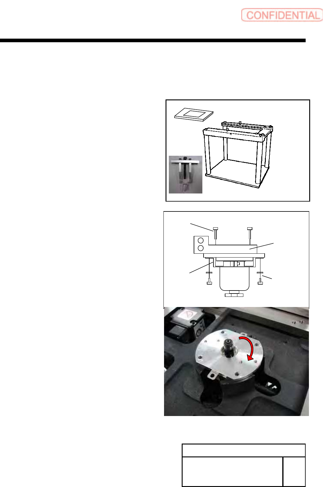
[Necessary Jigs]
Head Block
Assembly Plate (For G200)
Bearing remove JIG
[Disassembly]
1 For the removal procedure for the head unit.
Refer to RPGB-10301-1.
2 Remove the screws (2-CP3x4,2-W3).
3 Remove the screws (2-B3x16) and manifold.
4 Remove the encoder bearing holder.
1. Remove the screws (4-C3x8).
2. Rotate the encoder bearing holder to the
position of figure.
W3
CP3x4
Leaf
Spring
B3x16
Manifold
Change Procedure for Rotary
Encoder
RPGB-10701-1
SEET
1/5
Change Procedure for Rotary Encoder
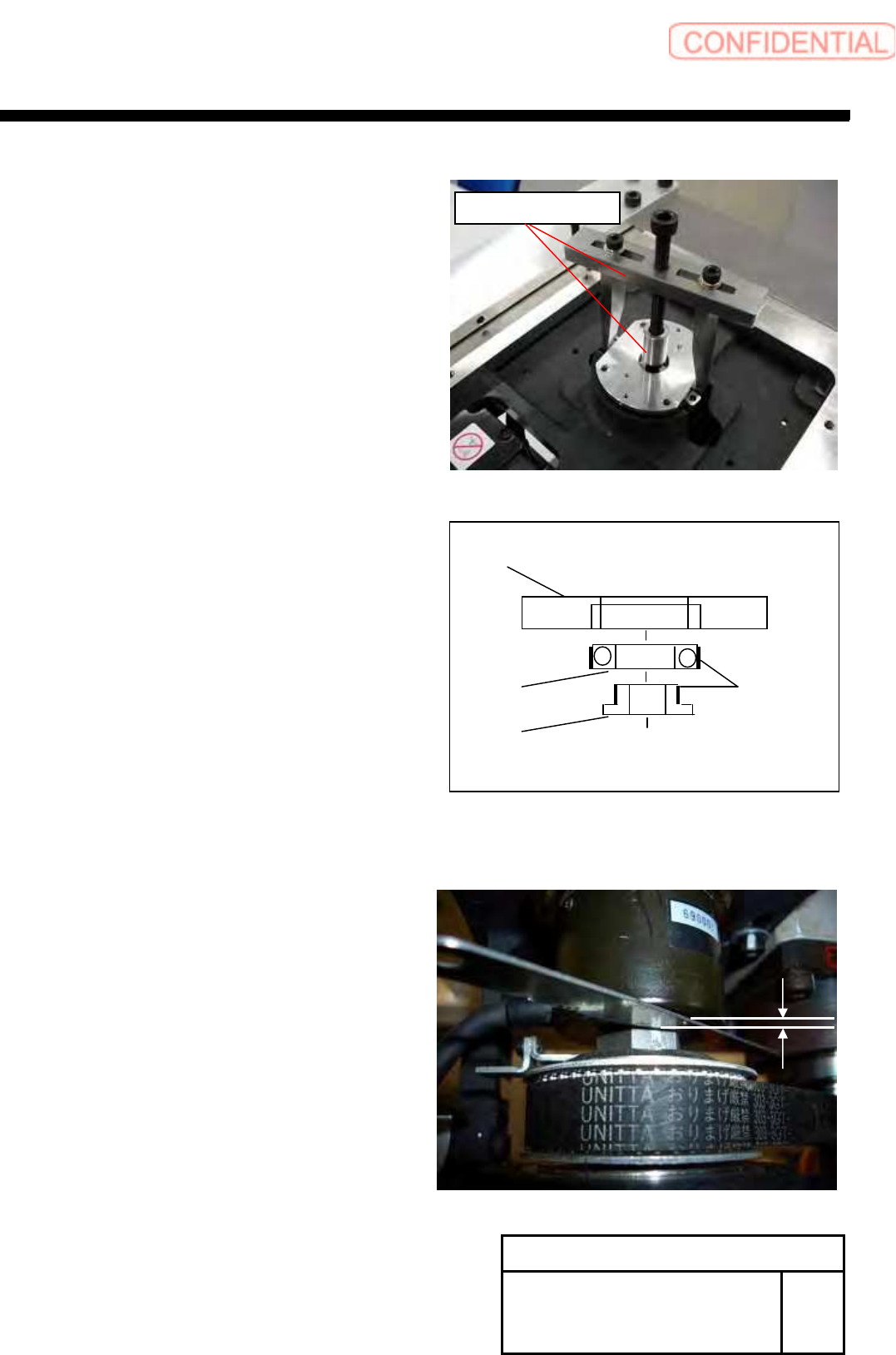
3. Attach the bearing remove JIG.
Remove the encoder bearing holder by slowly.
POINT
Please wipe the adhesive off after detaching.
(Bearing Holder, Bearing and Spacer)
5 Confirm the installation position of Encoder.
POINT
Measure the gap between Encoder and nut.
This data use as install of the encoder.
Change Procedure for Rotary
Encoder
RPGB-10701-1
SEET
2/5
Bearing
Encoder Bearing Holder
Spacer
Locktite
601
Bearing Remove JIG
Change Procedure for Rotary Encoder
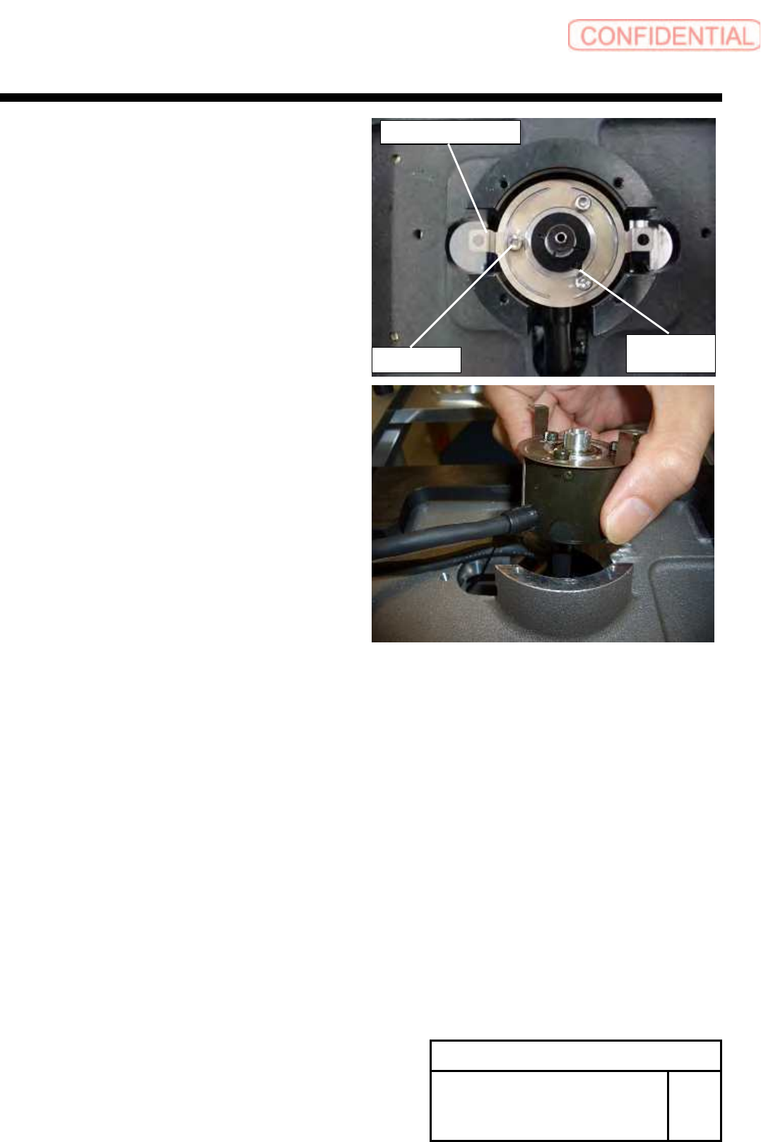
6
Remove the screws (3-C3x3, 3-W3), and remove
the Encoder Leaf Spring.
7 Loosen the screws (C2.5x8), and remove the Set Collar.
8 Pull out and detach the encoder.
Change Procedure for Rotary
Encoder
RPGB-10701-1
SEET
3/5
Set Collar
C2.5x8
C3x3,W3