MAN00000772_SI-G200BB_SVCPDFA.pdf - 第680页
Chan ge Pro cedu re for Ro tary En co der 13 Attach the enco der bearing ho lder. 1. Attach t he be aring and the spac er to the e ncode r bearing ho lde r. 2. Attach the co mple ted assy holde r by pushing slowly . 3. A…
Change Procedure for Rotary Encoder
[Reassembly]
9 Attach the Encoder Leaf Spring to the
New encoder with screws (3-C3x3, 3-W3).
10
Attach the encoder to the axis without stress to
the cable, and temporarily attach the set collar.
POINT
Insert it carefully in the direction of the Set collar.
The flat side should be attached on the upper side.
11
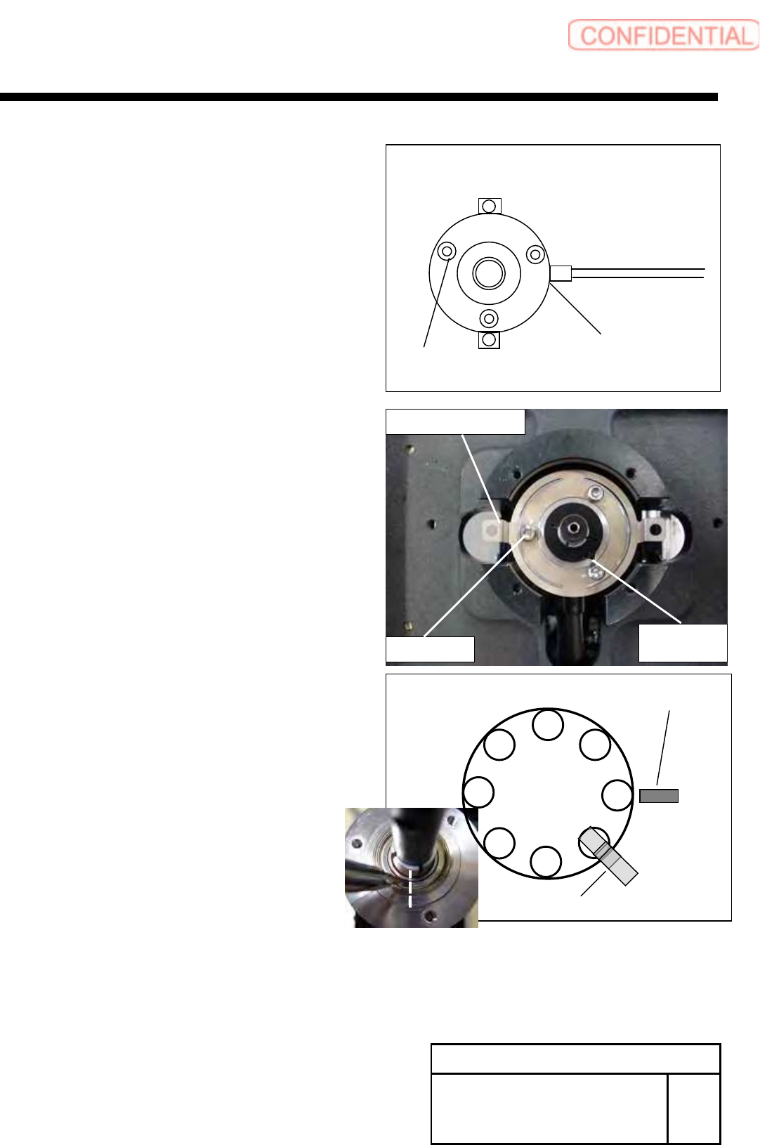
Adjust the position of RT axis and Z phase of the encoder.
1. Rotate the RT axis, adjust the No.2 shaft position to the
under the RT ORG sensor.
2.Adjust the Z phase position (marking-off line) of the encoder.
12 Adjust the gap between encoder and nut.
(measured by item 5)
Confirm the item 11 again.
Tighten the screw (C2.5x8), fix the encoder by set collar.
Change Procedure for Rotary
Encoder
RPGB-10701-1
SEET
4 /5
Cable Position
Installation
Position
C3
x
3
W3
Set Collar
C2.5×8
C3x3,W3
Encoder Leaf Spring
RT Dog
RT ORG Sensor
1
8
7
6
5
4
3
2
Change Procedure for Rotary Encoder
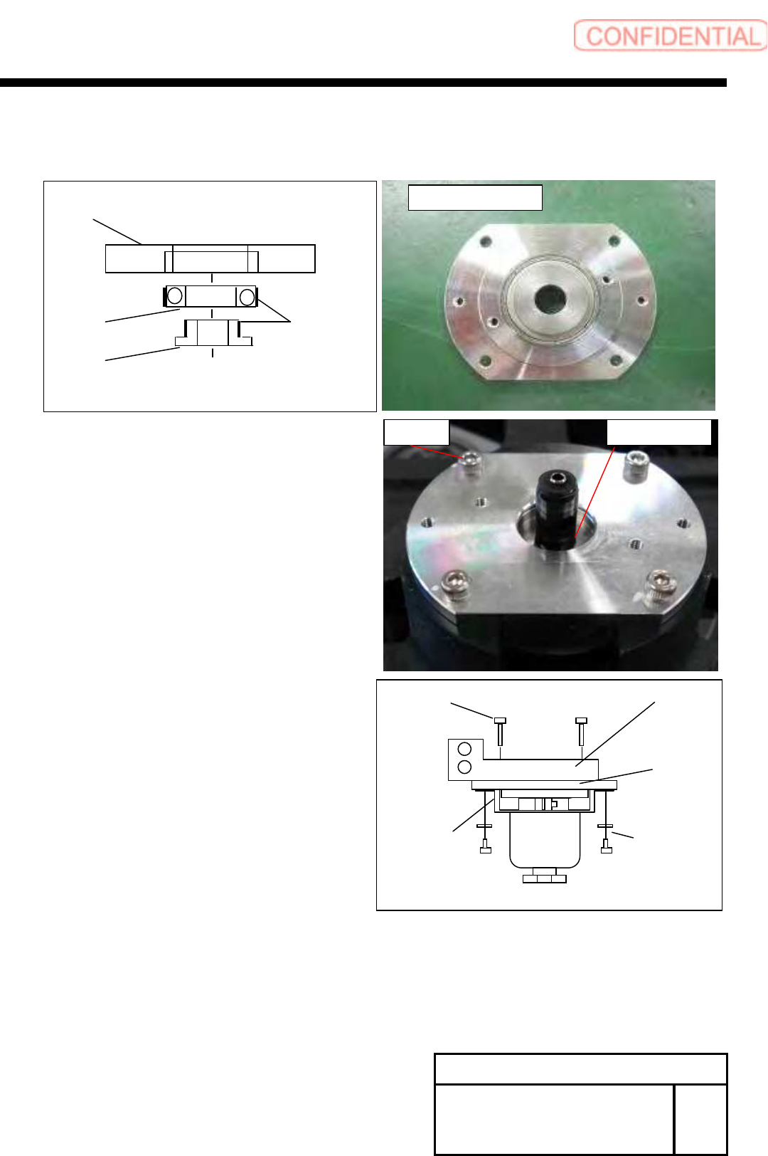
13 Attach the encoder bearing holder.
1. Attach the bearing and the spacer to
the encoder bearing holder.
2. Attach the completed assy holder by pushing slowly.
3. Apply the adhesive (Locktite601) to the inner of spacer.
4. Tighten the screws (4-C3x8).
14 Tighten the screws (3-C3x4, 3-W3) to lock
the encoder bearing holder.
15 Tighten the screws (2-B3x16), and attach the manifold.
16 Install the head unit. Refer to RPGB-10301-1
[Adjustment]
17 Calibration
1.HLGB-10202-01 Machine Setup
2.HLGB-10303-01 Calibration
Change Procedure for Rotary
Encoder
RPGB-10701-1
SEET
5 /5
Bearing
Encoder Bearing Holder
Spacer
Locktite
601
Completed Assy Holder
Locktite 601
C3x8
W3
CP3x4
Leaf
Spring
B3x16
Encoder
Bearing Holder
Manifold
Change Procedure for RN Axis Timing Belt
Change Procedure for RN Axis Timing Belt
[Necessary Jigs]
Tension meter (UNITTA U-507)
Tension adjustment JIG
[Disassembly]
1 Reset the machine to the origin.
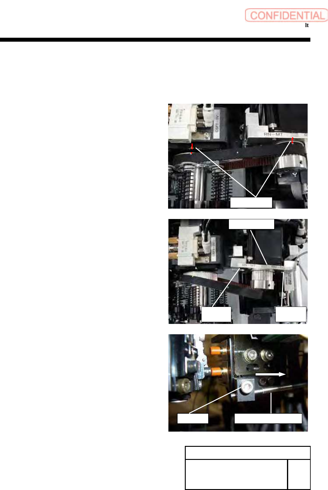
2 Put the restoration mark to the motor pulley
and the RN axis pulley.
3 Turn off the main power.
4 Open the front and rear slide doors of main.
5
Push the head base to the center.
6 Remove the screws (C5x20, C5x15, 2-W15), move the
RN motor bracket to the position in which the tension of
the timing belt loosens, and remove the timing belt from
the pulley on the motor side.
7 Loosen screws (C3x10), move the position of
Nozzle detect sensor.
Nozzle detect sensor
C3 x10
Change Procedure for RN-axis
Timing Belt
SHEET
1/3
RPGB-10801-1
Restoration mark
RN bracket
C5
x
20
W5
C5
x
15
W5