MAN00000772_SI-G200BB_SVCPDFA.pdf - 第682页
C h an ge Procedu re for R N-axi s Timin g Be l t 8 Remov e the inner shaf t, then mov e the positio n to under the H axis leve r. 9 Remov e the timing be lt thro ugh the gap betwe en H ax is leve r and plunge r. Ch ange…
Change Procedure for RN Axis Timing Belt
Change Procedure for RN Axis Timing Belt
[Necessary Jigs]
Tension meter (UNITTA U-507)
Tension adjustment JIG
[Disassembly]
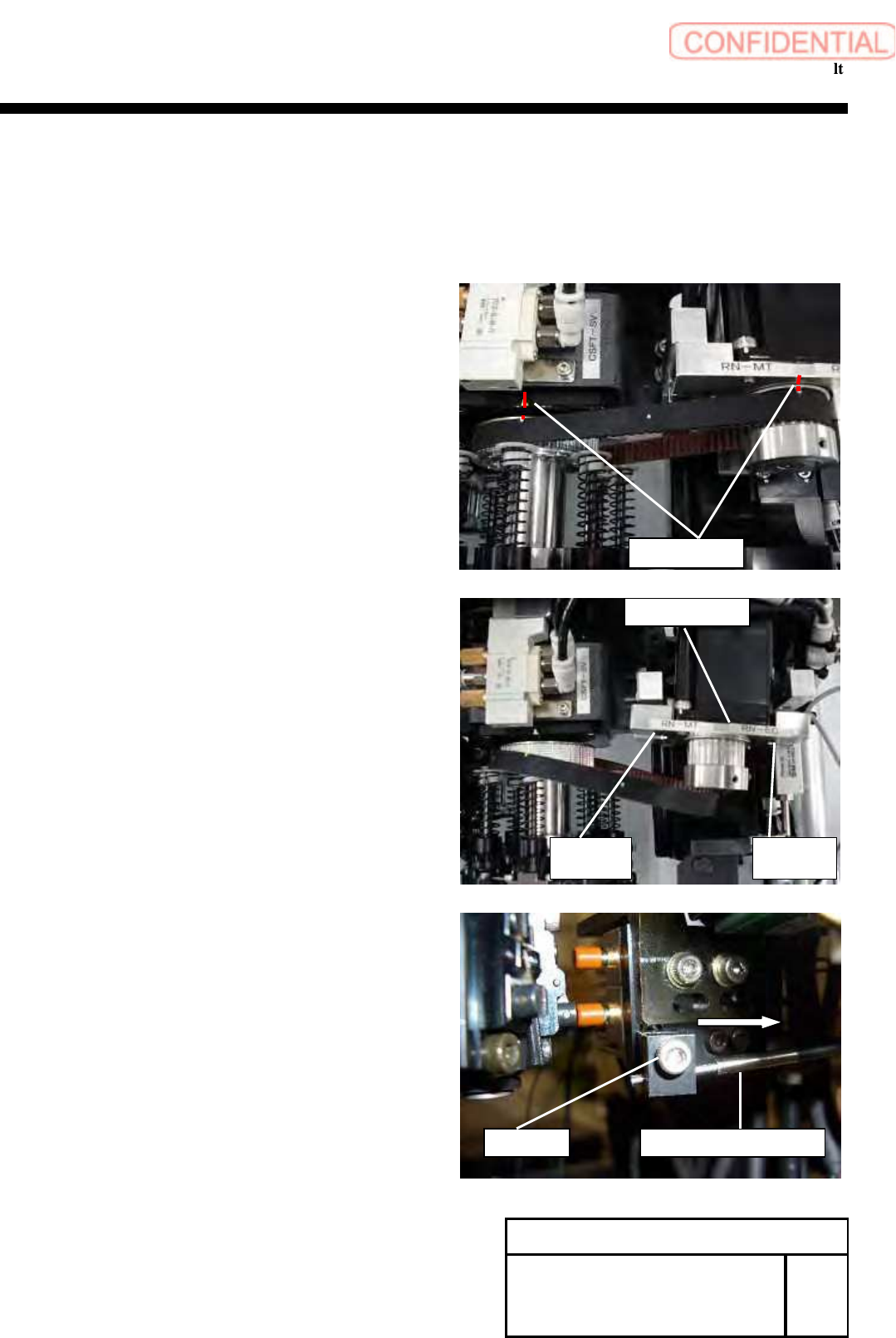
1 Reset the machine to the origin.
2 Put the restoration mark to the motor pulley
and the RN axis pulley.
3 Turn off the main power.
4 Open the front and rear slide doors of main.
5
Push the head base to the center.
6 Remove the screws (C5x20, C5x15, 2-W15), move the
RN motor bracket to the position in which the tension of
the timing belt loosens, and remove the timing belt from
the pulley on the motor side.
7 Loosen screws (C3x10), move the position of
Nozzle detect sensor.
Nozzle detect sensor
C3 x10
Change Procedure for RN-axis
Timing Belt
SHEET
1/3
RPGB-10801-1
Restoration mark
RN bracket
C5
x
20
W5
C5
x
15
W5
Change Procedure for RN-axis Timing Belt
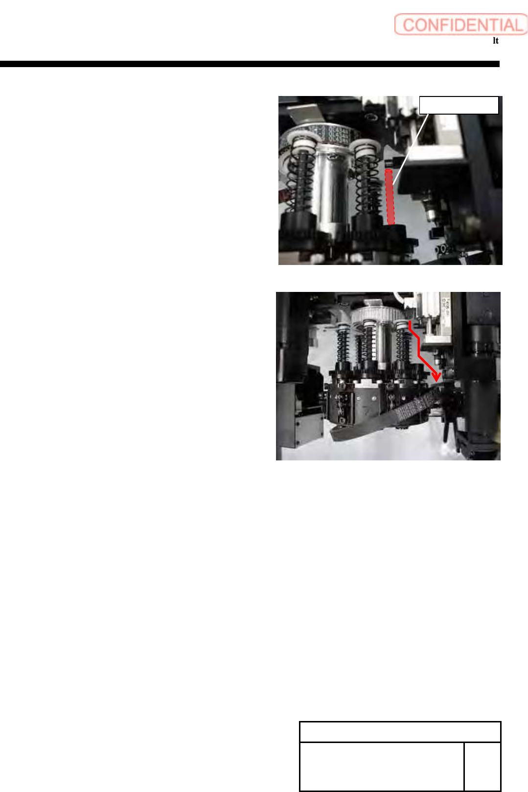
8
Remove the inner shaft, then move the position
to under the H axis lever.
9
Remove the timing belt through the gap between
H axis lever and plunger.
Change Procedure for RN-axis
Timing Belt
SHEET
2/3
RPGB-10801-1
Inner Shaft
Change Procedure for RN axis Timing Belt
[Reassembly]
10 Apply the new timing belt to pulley on the head
side in the reverse order of the above procedure.
11 Apply the RN timing belt to the pulley on the motor side.
1. Confirm the condition of item 2 again.
Temporarily attach the RN bracket.
12 Adjust the tension of RN timing belt, refer to RPGB-10501-1
.
13 Attach the inner shaft. (Removed it item8)
[Adjustment]
14 Adjust the nozzle detection sensor position.
Refer to HLGB-10413-01.
15 Calibration
1. HLGB-10207-01 RN ORG Offset Setting
2. HLGB-10414-01 Nozzle Phase Adjustment
3. HLGB-10304-01 Calibration
Change Procedure for RN-axis
Timing Belt
SHEET
3/3
RPGB-10801-1